The Grid-of-Dots Calibration Plate
The Calibration tool works by acquiring an image of a calibration plate that you provide. The calibration plate provides the physical reference for the calibration.
The calibration plate you construct must meet the following requirements:
- It must consist of a two-dimensional grid of dots.
- The dots must be circular.
- The diameter of the dots must be no greater than one-half of the smaller of the x-axis dot pitch or the y-axis dot pitch.
- The diameter of the dots must be at least 10 pixels.
- The edge of the calibration plate should be outside of the acquired image.
The figure below shows an example of a grid-of-dots calibration plate suitable for use with the Grid-of-Dots Calibration tool.

Grid-of-dots calibration plate
You can optionally include a pair of rectangles that meet the following requirements:
- The length of the rectangles must be 2 times the grid pitch in the direction of the rectangle.
- The rectangles must be perpendicular to each other.
- The intersection of the two lines drawn through the centers of the two rectangles must fall at the center of a grid cell.
The Grid-of-Dots Calibration tool lets you use the point defined by the intersection of the lines drawn through the two rectangles as an anchor point for the physical coordinate system.
The figure below shows an example of a calibration plate that includes the two rectangles. (The dotted lines in the figure below are not part of the plate but are drawn to show the location of the anchor point.)
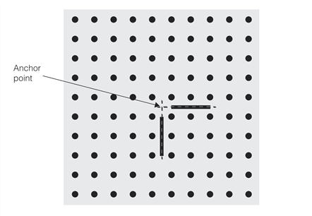
Grid-of-dots calibration plate with anchor point