Grounding
Grounding and Shielding Concept
Field bus and I/O part of the DMA-EZCCM-001 modules can be grounded separately.
-
The grounding clamp at the M8 connectors for the fieldbus connection (P1, P2) connects the shield of the fieldbus lines.
- The grounding ring leads the shield at the flange of the M8 connectors for the fieldbus connection via an RC-circuit to the outside of the station.
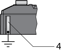
- By mounting the module onto a mounting plate through the mounting hole, the module is connected to the reference potential of the installation by a metal screw.
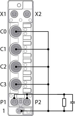
- The spacers TBNN-S0-DRS1 for mounting the DMA-EZCCM-001 modules onto a DIN rail (TS 35) connect the grounding contact of the modules with the DIN rail and thus with FE.
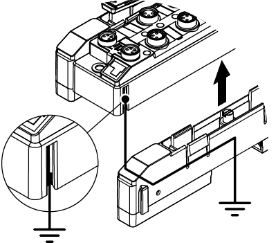
Ground the Device (FE)
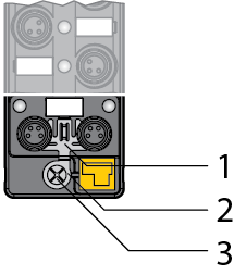
To shield the network cables from possible noise interference the flange of the M8 connectors needs to be at the reference potential of the installation.
This is done through the grounding ring and clamp that are mounted on the device by default and which need to be connected with a metal screw when mounting on a DIN rail.
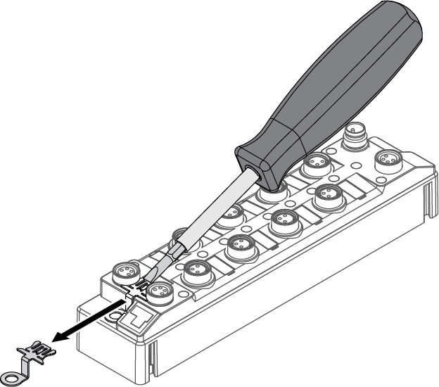
Removing the Grounding Clamp
Use a flat screwdriver to slide the grounding clamp forward and remove it.
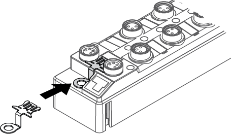
Mounting the Grounding Clamp
Insert the grounding clamp between the fieldbus connectors (using a screwdriver if necessary) so that it contacts the metal housing of the connector.
The shielding of the fieldbus lines is now connected to the grounding clamp.