Object Model
The ID Reader Object is a vendor specific object class. This means that it is not part of the CIP common (public) architecture but an extension. It is a custom object that Cognex has added to the EtherNet/IP architecture on the DataMan device. All the data and functionality of this object model are available in the DataMan reader. This includes triggering, status, events, errors, and result data.
The ID Reader Object is identified by its vendor specific class code:
DataMan ID Reader Object Class Code: 0x79
Objects are made up of attributes (data) and services (functionality). These can be defined at the class level (common to all instances of the class) or the instance level (unique to an individual instance). The CIP specification defines common attributes and services that apply to all objects (often these are optional). Vendors may also define their own attributes and services for their vendor specific classes.
The ID Reader Object attributes and services can be individually accessed via explicit messaging. In addition, a number of the ID Reader Object attributes are exposed in the DataMan assembly objects which allow them to be accessed as a group via implicit messaging.

Attributes
The DataMan ID Reader Object (Class Code: 0x79) has the following attributes:
| Attribute ID | Access Rule | Name | Data Type | Description |
|---|---|---|---|---|
| 0x9 | Set | AcqTriggerEnable | BOOL |
0 = EtherNet/IP triggering is disabled 1 = EtherNet/IP triggering is enabled |
| 0xA | Set | AcqTrigger | BOOL | Acquire an image when this attribute changes from 0 to 1. |
| 0xB | Get | AcqStatusRegister | BYTE |
Bit0: Trigger Ready Bit1: Trigger Ack Bit2: Reserved Bit3: Missed Acquisition Bit4-7: Reserved |
| 0xC | Set | UserData | ARRAY of BYTE | User defined data that can be used as an input to the acquisition/decode. |
| 0xD | Set | BufferResultsEnable | BOOL | When true, it enables buffering of the decode results. |
| 0xE | Get | DecodeStatusRegister | BYTE |
Bit0: Decoding Bit1: Decode completed (toggle) Bit2: Results buffer overrun Bit3: Results available Bit4: Reserved Bit5: Reserved Bit6: Reserved Bit7: General fault indicator |
| 0xF | Set | ResultsAck | BOOL | Acknowledges that the client received the decode results. |
| 0x10 | Get | DecodeResults | STRUCT of | The last decode results. |
| ResultsID | UINT |
Decode results identifier. Corresponds to the TriggerID of the decoded image. |
||
| ResultCode | UINT |
Decode result summary code value. Bit0: 1=Read, 0=No read Bit1: 1=Validated, 0=Not Validated Bit2: 1=Verified, 0=Not Verified Bit3: 1=Acquisition trigger overrun Bit4: 1=Acquisition buffer overrun Bit5-15: Reserved (future use) |
||
| ResultExtended | UINT | Extended result information. | ||
| ResultLength | UINT | Current number of result data bytes. | ||
| ResultData | ARRAY of BYTE | Result data from last decode. | ||
| 0x12 | Set | SoftEvents | BYTE |
SoftEvents act as virtual inputs (execute action on 0 to 1 transition) Bit0: Train code Bit1: Train match string Bit2: Train focus Bit3: Train brightness Bit4: Un-Train Bit5: Reserved (future use) Bit6: Execute DMCC command Bit7: Set match string |
| 0x15 | Get | TriggerID | UNIT | Trigger identifier. ID of the next trigger to be issued. |
| 0x16 | Set | UserDataOption | UINT | Optional user data information. |
| 0x17 | Set | UserDataLength | UINT | Current number of user data bytes. |
| 0x18 | Get | SoftEventAck | BYTE |
Acknowledgment of SoftEvents. Bit0: Train code ack Bit1: Train match string ack Bit2: Train focus ack Bit3: Train brightness ack Bit4: Un-Train ack Bit5: Reserved (future use) Bit6: Execute DMCC command ack Bit7: Set match string ack |
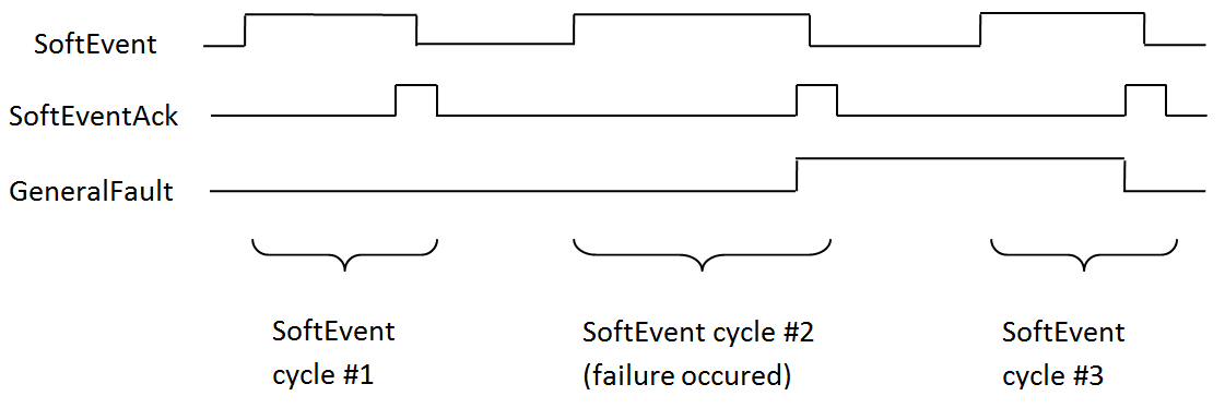
SoftEvents
SoftEvents act as “virtual” inputs. When the value of a SoftEvent changes from 0 to 1, the action associated with the event is executed. When it is done, the corresponding SoftEventAck bit changes from 1 to 0 to mark completion.
The SoftEvent and SoftEventAck form a logical handshake. After SoftEventAck changes to 1 the original SoftEvent is set back to 0. When that occurs, SoftEventAck is automatically set back to 0.
The “ExecuteDMCC” and “SetMatchString” SoftEvent actions require user supplied data. This data must be written to the UserData and UserDataLength area of the Input Assembly prior to invoking the SoftEvent. Since both of these SoftEvents depend on the UserData, only one can be invoked at a time.
General Fault Indicator
When a communication related fault occurs, the “GeneralFault” bit changes from 0 to 1. The only fault conditions supported are SoftEvent operations. If a SoftEvent operation fails, the fault bit will be set. The fault bit remains set until either the next successful SoftEvent operation or until TriggerEnable is set to 0 and then back to 1.
|
Services
The ID Reader Object supports the following Common CIP services:
| Service Code | Service Name | Description |
|---|---|---|
| 0x05 | Reset | Resets the ID Reader object. |
| 0x0E | Get_Attribute_Single | Returns the contents of the specified attribute. |
| 0x10 | Set_Attribute_Single | Modifies the specified attribute. |
The ID Reader Object supports the following vendor specific services:
| Service Code | Service Name | Description |
|---|---|---|
| 0x32 | Acquire | Triggers a single acquisition. |
| 0x34 | SendDMCC | Sends a DMCC command to the device. |
| 0x35 | GetDecodeResults | Gets the content of the DecodeResults attribute. |
Acquire Service
The Acquire Service triggers an acquisition (if the acquisition system is ready to acquire an image). If the acquisition could not be triggered, then the Missed Acquisition bit of the AcqStatusRegister will be set until the next successful acquisition.
SendDMCC Service
The SendDMCC Service sends a DMCC command string to the device. The request data consists of the DMCC command string that is to be sent to the reader. The reply data will contain the string result of the DMCC command. Additionally, the service provides a numeric result status for the call. Most of these result codes relate to the basic success/failure of the service execution. However, the service also maps the actual DMCC status codes. This allows the PLC to interpret the service request without having to parse the actual DMCC return string.
DMCC commands transferred through the Industrial Ethernet protocols are automatically routed to the Wi-Fi reader. The commands cannot be executed while the Wi-Fi reader is powered off, hibernating, or out-of-range.
| Service Return Code |
Description | DMCC Return Code |
|---|---|---|
| 0 | Success – No error | 0 |
| 1 | Bad Command | - |
| 4 | No Answer – System too busy | - |
| 100 | Unidentified error | 100 |
| 101 | Command invalid | 101 |
| 102 | Parameter invalid | 102 |
| 103 | Checksum incorrect | 103 |
| 104 | Parameter rejected/altered due to reader state |
104 |
GetDecodeResults Service
The GetDecodeResults service reads data from the DecodeResults attribute of the ID Reader Object. This service takes parameters indicating the “size” (number of bytes to read) and the “offset” (offset into the DecodeResults attribute to begin reading). This gives the service the flexibility to be used with PLCs that have different restrictions on the amount of data allowed in an explicit message. It also allows you to access very large codes that cannot be completely transferred with implicit messaging (assembly object).
GetDecodeResults Request Data Format
| Name | Type | Description |
|---|---|---|
| Size | UINT | The number of bytes of the DecodeResults attribute to read. |
| Offset | UINT | The offset into the DecodeResults attribute. This specifies the first byte of the DecodeResults attribute to begin reading (0 based offset). |
Acquisition Sequence
DataMan can be triggered to acquire images by several methods. It can be done either implicitly through the Assembly object, or done explicitly through the ID Reader object. When using explicit messaging, you can either:
- access the Acquire Service in a single step, or
- directly manipulate the ID Reader object attributes (AcqTrigger and AcqStatusRegister), or
- use DMCC commands.
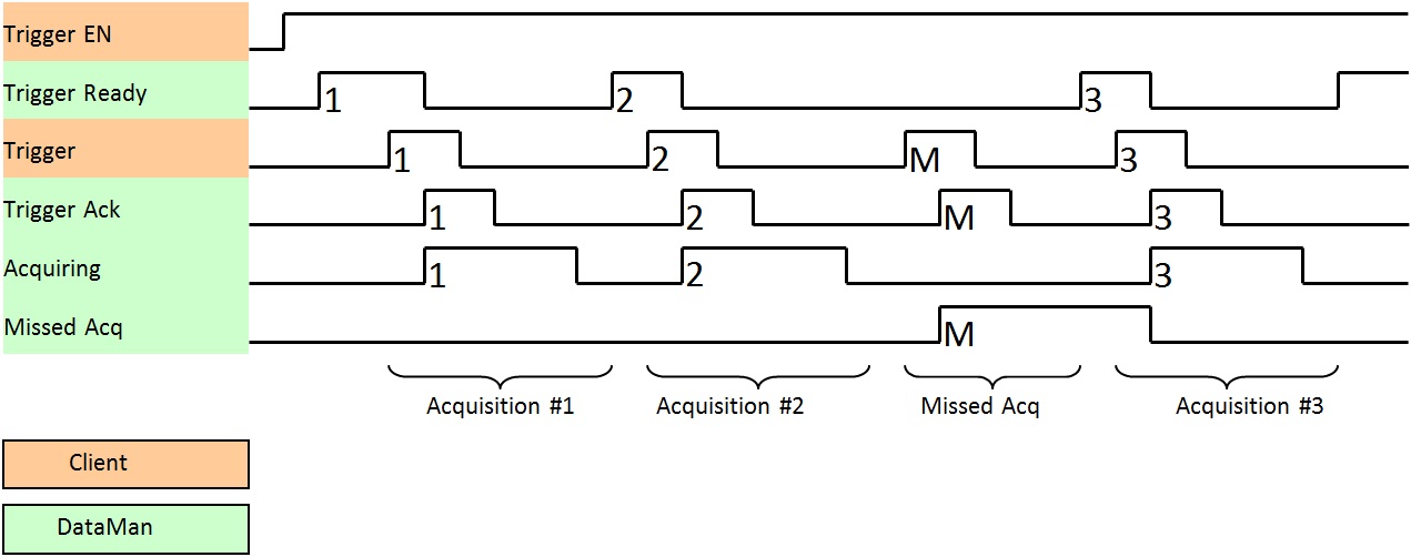
The ID Reader attributes are discussed in this section. These same values can also be accessed through the assembly objects. On startup, the AcqTriggerEnable attribute is False. Set the attribute to True to enable triggering. When the device is ready to accept triggers, the Trigger Ready bit in the AcqStatusRegister is set to True.
While the AcqStatusRegister “Trigger Ready” bit is True, each time the ID Reader object sees the AcqTrigger attribute change from 0 to 1, it initiates an image acquisition. When setting the Trigger Ready bit to True through the assembly objects, make sure that the attribute is held in the new state until that same state value is seen in the Trigger Ack bit of the AcqStatusRegister (this is a necessary handshake to guarantee that the change is seen by the ID Reader object).
During an acquisition, the Trigger Ready bit in the AcqStatusRegister is cleared and the Acquiring bit is set to True. When the acquisition is completed, the Acquiring bit is cleared. The Trigger Ready bit is again set to True once the device is ready to begin a new image acquisition.
If results buffering is enabled, the device will allow overlapped acquisition and decoding operations. Trigger Ready is set high after acquisition is complete but while decoding is still in process. This can be used to achieve faster overall trigger rates. If result buffering is not enabled, the Trigger Ready bit will remain low until both the acquisition and decode operations have completed.
In certain cases, you can cancel an acquisition by clearing the Trigger signal before the read operation is finished. This allows you to cancel reads in Presentation and Manual mode if no code is in the field of view. To ensure that a read is not unintentionally cancelled, make sure that the PLC holds the Trigger signal True until both TriggerAck and ResultsAvailable are True (or DecodeComplete toggles state).
|
To force a reset of the trigger mechanism, set the AcqTriggerEnable attribute to False until the AcqStatusRegister is 0. Then the AcqTriggerEnable can be set to True to re-enable acquisition.
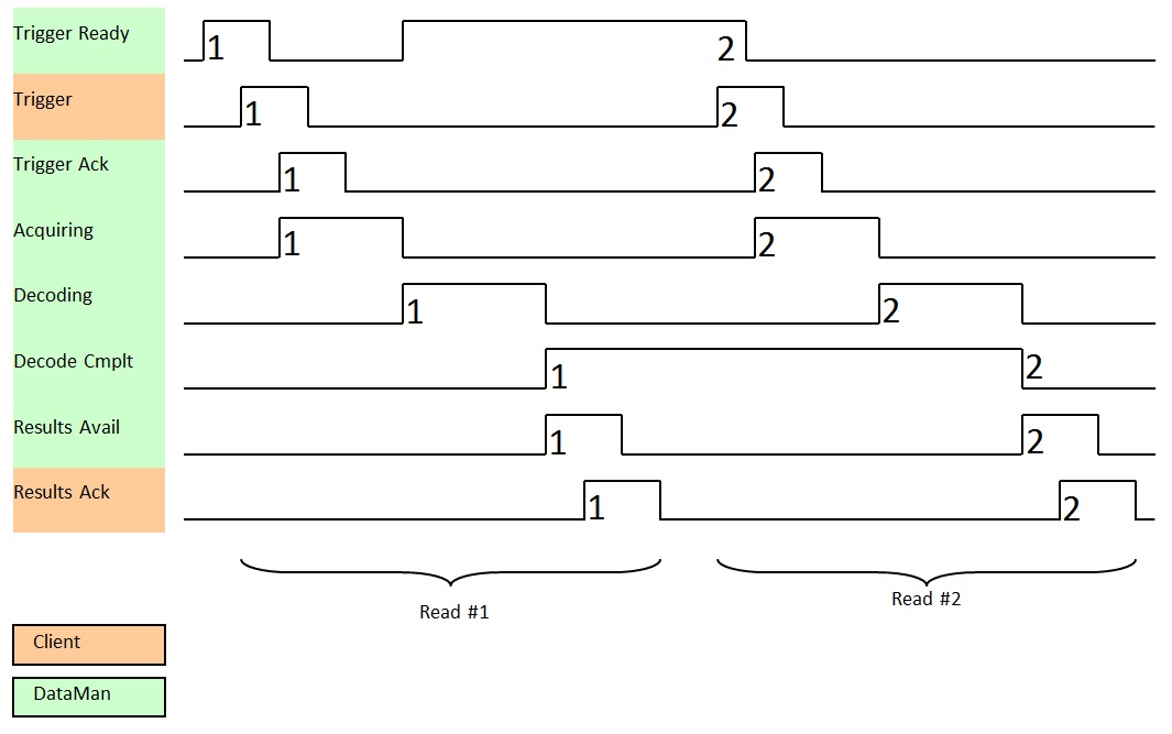
Decode / Result Sequence
After an image is acquired, it is decoded. While being decoded, the Decoding bit of the DecodeStatusRegister is set. When the decode is complete, it clears the Decoding bit and toggles the Decode Completed bit.
The BufferResultsEnable attribute determines how the ID Reader Object handles decode results. If the BufferResultsEnable attribute is set to False, then the decode results are immediately placed into the DecodeResults attribute, and Results Available is set to True.
If the BufferResultsEnable attribute is set to True, the new results are queued. The earlier decode results remain in the DecodeResults attribute until they are acknowledged by the client setting the ResultsAck attribute to True. After the Results Available bit is cleared, the client sets the ResultsAck attribute back to False to allow the next queued results to be placed in to the DecodeResults attribute. This is a necessary handshake to ensure that the DataMan reader's client (PLC) receives the results.
Behavior of DecodeStatusRegister
| Bit | Bit Name | Results if Buffering Disabled | Results if Buffering Enabled |
|---|---|---|---|
| 1 | Decoding | Set when decoding an image. | Set when decoding an image. |
| 2 | Decode Complete | Toggled on completion of an image decode. | Toggled on completion of an image decode. |
| 3 | Results Buffer Overflow | Remains set to zero. | Set when decode results could not be queued because the client failed to acknowledge a previous result. Cleared when the decode result is successfully queued. |
| 4 | Results Available | Set when new results are placed in the DecodeResults attribute. Stays set until the results are acknowledged by setting ResultsAck to true. | Set when new results are placed in the DecodeResults attribute. Stays set until the results are acknowledged by setting ResultsAck to true. |
|
Results Buffering
There is an option to enable a queue for decode results. Enabling it allows a finite number of decode result data to queue up until the client (PLC) has time to read them. This is useful to smooth out data flow if the client (PLC) slows down for short periods of time.
If result buffering is enabled, the device will allow overlapped acquisition and decode operations. Depending on the application this can be used to achieve faster overall trigger rates. See Acquisition Sequence description above for more details.
If reads occur faster than results can be sent out, the primary difference between buffering or not buffering is determining which results get discarded. If buffering is not enabled, the most recent results are kept and the earlier result (which was not read by the PLC fast enough) is lost, because the more recent result will overwrite the earlier result. If buffering is enabled (and the queue becomes full) the most recent results are discarded until space becomes available in the results queue.
Assembly Object
Assemblies are combinations of selected attributes (data items) from CIP objects within a device. The device vendor defines assemblies according to their needs and combine data together in useful groupings according to the requirements of the application.
DataMan is an I/O adapter class device. The convention for adapters is that Input Assemblies produce (transmit) data for another device (that is, DataMan to PLC) and Output Assemblies consume (receive) data from another device (that is, PLC to DataMan). DataMan acts as an I/O module for another device such as a PLC.
Assembly objects use implicit messaging. They are blocks of data which are transmitted as the raw payload of implicit messaging packets. These implicit messaging packets are produced (transmitted) repeatedly at a predefined chosen rate (for example, 100ms or 200ms).
DataMan readers have a single input assembly and single output assembly. These assemblies combine selected attributes (data) of the DataMan ID Reader Object into groupings that minimize network bandwidth, and still allow for efficient control and processing. The data in these assemblies can also be accessed individually from the ID Reader Object. However, using the assembly objects is much more efficient, thus they are the primary means of runtime communication between a DataMan reader and a PLC.
Input Assembly
The Input assembly provides status information, process state, and decode results.
| Instance | Byte | Bit 7 | Bit 6 | Bit 5 | Bit 4 | Bit 3 | Bit 2 | Bit 1 | Bit 0 |
|---|---|---|---|---|---|---|---|---|---|
| 11 | 0 | Reserved | Missed Acq |
Acquiring |
Trigger Ack |
Trigger Ready |
|||
| 1 |
General Fault |
Reserved |
Results Available |
Results Buffer Overrun |
Decode Complete Toggle |
Decoding | |||
| 2 |
SoftEvent Ack 7 |
SoftEvent Ack 6 |
SoftEvent Ack 5 |
SoftEvent Ack 4 |
SoftEvent Ack 3 |
SoftEvent Ack 2 |
SoftEvent Ack 1 |
SoftEvent Ack 0 |
|
| 3-5 | Reserved | ||||||||
| 6 | Trigger ID (16-bit integer) | ||||||||
| 7 | |||||||||
| 8 | Result ID (16-bit integer) | ||||||||
| 9 | |||||||||
| 10 | Result Code (16-bit integer) | ||||||||
| 11 | |||||||||
| 12 | Result Extended (16-bit integer) | ||||||||
| 13 | |||||||||
| 14 | Result Data Length (16-bit integer) | ||||||||
| 15 | |||||||||
| 16 | Result Data 0 | ||||||||
| ... | |||||||||
| 499 | Result Data 483 | ||||||||
Output Assembly
The Output assembly contains control signals, software event signals, and any user data required for the trigger and decode.
| Instance | Byte | Bit 7 | Bit 6 | Bit 5 | Bit 4 | Bit 3 | Bit 2 | Bit 1 | Bit 0 |
|---|---|---|---|---|---|---|---|---|---|
| 21 | 0 | Reserved |
Results Ack |
Buffer Results Enable |
Trigger |
Trigger Enable |
|||
| 1 |
SoftEvent 7 |
SoftEvent 6 |
SoftEvent 5 |
SoftEvent 4 |
SoftEvent 3 |
SoftEvent 2 |
SoftEvent 1 |
SoftEvent 0 |
|
| 2 | Reserved | ||||||||
| 3 | |||||||||
| 4 | User Data Option (16-bit integer) | ||||||||
| 5 | |||||||||
| 6 | User Data Length (16-bit integer) | ||||||||
| 7 | |||||||||
| 8 | User Data 0 | ||||||||
| ... | |||||||||
| 499 | User Data 491 | ||||||||
PCCC Object
DataMan has limited support for the Rockwell PCCC object. This allows legacy PLCs (PLC-5, SLC, and so on) to communicate with DataMan using their native PCCC command set and explicit messaging. The PCCC object allows DataMan to look like a Rockwell PLC-5 logic controller.
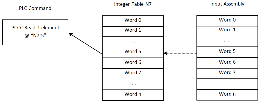
PCCC commands are organized to work with “data tables” that exist in legacy logic controllers. Each data table is an array of a give data type (BYTE, INT, FLOAT, and so on). The commands are oriented to read/write one or more data items of a given data table. Items are addressed by specifying the data table and the index of the item in the table (indexes base from 0). For instance, to read the 6th integer in PLC data table, you need to send the PCCC command to read N7:5. “N” specifies an integer table, “7” is the table number in the PLC (each table has a unique numeric identifier – assigned when the user PLC program was created), and “5” is the index into the table (note indexes begin at 0).
The PCCC object in DataMan maps the read and write requests to ID Reader assemblies, or in one special case to the DMCC service. Read commands return data from the Input assembly (instance 11). Write commands send data to the Output assembly (instance 21). The implementation only supports an Integer data table (N7) and an ASCII data table (A9). There is one special case of String data table (ST10:0) for DMCC.
| Table | Data Type | Table Size |
|---|---|---|
| N7 | Integer (16-bit) | 250 elements |
| A9 | ASCII (8-bit) | 500 elements |
| ST10 | String | 1 element |
The ResultCode value is located at word offset 5 (counting from 0) of the Input Assembly. To access this value, issue the following PLC command:
|
The decode ResultData begins at byte offset 16 (counting from 0) of the Input Assembly. To read the first 4 bytes of result data, issue the following PLC command:
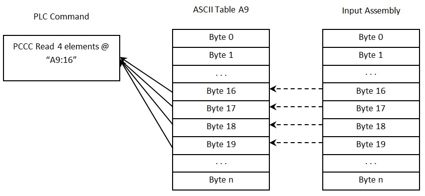
|
The UserData begins at word offset 4 (counting from 0) of the Output Assembly. To write 4 words of UserData, issue the following PLC command:
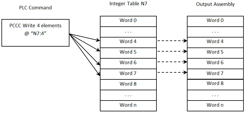
|
The bit to trigger an acquisition is in byte offset 0 of the Output Assembly. To write to this byte, issue the following PLC command:
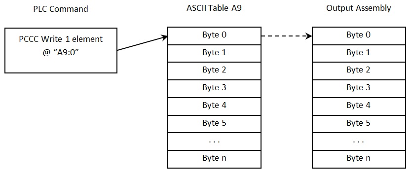
|
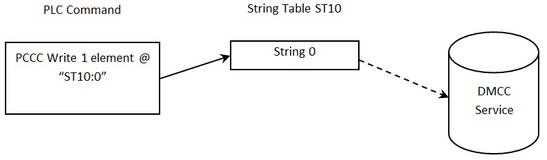
The PCCC Object supports a special case mapping of a string table element (ST10:0) to the DMCC service. Any string written to ST10:0 is passed to the DMCC service for processing. This allows PCCC write string commands to be used to invoke DMCC commands.
|