Trigger and Laser Enable Inputs
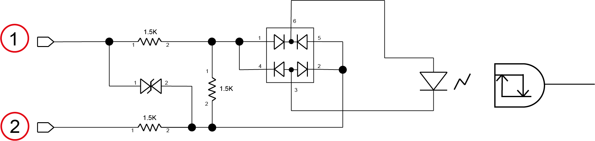
The acquisition trigger and laser enable inputs to the sensor are opto-isolated. The sensor responds to a trigger event when the voltage difference between the TRIGGER and IN COMMON inputs exceed 10 V. The laser enable input is enabled when the difference between the LASER ENABLE and IN COMMON inputs exceed 10 V.
To configure the acquisition trigger and laser enable as NPN ´(current sinking) inputs, connect the TRIGGER and LASER ENABLE terminals to the output of the sensors and the IN COMMON terminal to the return of the sensor. The TRIGGER or LASER ENABLE terminal set to a high voltage level (12 V ‑24 V) causes the current flow through the LED emitter of the opto-isolator, turning on the corresponding opto-coupler output.
To configure the acquisition trigger and laser safety as PNP (current sourcing) inputs, connect the TRIGGER and LASER ENABLE terminals to the return of the sensors and the IN COMMON terminal to the sensor voltage reference (12 V‑24 V). The TRIGGER or LASER ENABLE terminal set to ground level (12V – 24V) causes the current to flow through the LED emitter of the opto-isolator, turning on the corresponding opto-coupler output.
|
|
|---|---|
| Number | Input |
|
1 |
TRIGGER |
|
2 |
IN COMMON |