EtherNet/IP Object Model and Input/Output Assembly Objects
This topic covers the In-Sight Object Model for In-Sight vision systems running In-Sight firmware 5.1.0 and later.
In-Sight Object Model
In EtherNet/IP networks, In-Sight vision systems act as servers, with support for both explicit and implicit I/O messaging. Data from inspections, for instance, can be transferred to clients via explicit messages or through implicit connections. Implicit connections can also be used to control acquisitions, triggers and spreadsheet events.
The Identity Object, Ethernet Link Object, TCP/IP Object and the Other Internal Objects are required by the EtherNet/IP specification. The different instances of the Assembly Object are used to exchange application data with EtherNet/IP clients. The Vision Object is defined by the In-Sight System to provide information specific to In-Sight vision systems. The details for how this occurs are provided in the Vision Object Attributes and Services section. The current object model provided by In-Sight vision systems is illustrated in the following figure:
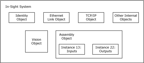
- Assembly Object: The Assembly Object binds attributes of multiple objects, which allows data to and from each object to be sent or received over a single connection. Assembly Objects can be used to bind input data or output data. The terms "input" and "output" are defined from the network's point of view. An "input" will produce data on the network and an "output" will consume data from the network.
- Identity Object: This object provides identification of, and general information about, the device.
- Ethernet Link Object: The Ethernet Link Object maintains link-specific counters and status information for an Ethernet 802.3 communications interface.
- TCP/IP Object: The TCP/IP Object provides a mechanism to query and possibly configure a device's TCP/IP network interface configuration. Examples of items of interest include a device's IP Address, Network Mask and Gateway Address.
- Vision Object: The Vision Object contains all of the services and attributes specific to In-Sight vision systems. This includes acquisition, inspection, job change-over and communications with the In-Sight Explorer spreadsheet.
Input and Output Assembly Objects
The I/O Assembly data attribute for the input and output data has the following formats:
| Firmware Version | Input Assembly | Output Assembly |
|---|---|---|
| Instance | Instance | |
| 5.1.0 and higher |
13 Note: For more information, see Input
Assemblies - Instance 13.
|
22 Note: For more information, see I/O Assembly Data Attribute Format - Output Assemblies - Instance 22.
|
- If using an EDS generated profile, although the maximum size of the Input Assembly is 500 bytes, the EDS generated profile will only allow a connection of up to 496 bytes.
- When using Rockwell RSLogix Studio 5000, version 21 through 25, the In-Sight EDS generated profile’s default Input and Output Assembly sizes (496 bytes for each) cannot be edited and will default to the largest Input and Output Assembly sizes.
- The Acquisition ID will increment at the beginning of acquisition, when the Trigger Ack is generated and sent to the PLC. The Inspection ID increments when the Inspection Completed bit toggles (at which time the Results Valid is set high and the Inspecting bit goes low).
- For differences in the Input and Output Assembly tables when migrating from In-Sight vision systems running In-Sight 4.x.x firmware to vision systems running 5.x.x firmware, see Input/Output Assembly Changes.
Input Assemblies - Instance 13
| Instance | Byte | Bit 7 | Bit 6 | Bit 5 | Bit 4 | Bit 3 | Bit 2 | Bit 1 | Bit 0 |
|---|---|---|---|---|---|---|---|---|---|
| 13 | 0 | Online |
Offline Reason |
Missed Acq |
Reserved |
Trigger Ack |
Trigger Ready |
||
| 1 | Error |
Command Failed |
Command Completed |
Command Executing |
Results Valid |
Results Buffer Overrun |
Inspection Completed |
System Busy |
|
| 2 | Reserved | Reserved |
Reserved (5.1.0 - 5.5.x)
|
Job Pass |
Exposure Complete |
Reserved | Reserved |
Set User Data Ack |
|
| TestRun Ready (5.6.0 and later) | |||||||||
| 3 |
Soft Event Ack 7 |
Soft Event Ack 6 |
Soft Event Ack 5 |
Soft Event Ack 4 |
Soft Event Ack 3 |
Soft Event Ack 2 |
Soft Event Ack 1 |
Soft Event Ack 0 |
|
| 4 | Error Code (16-bit integer) | ||||||||
| 5 | |||||||||
| 6 | Reserved (16-bit integer) | ||||||||
| 7 | |||||||||
| 8 | Current Job ID (16-bit integer) | ||||||||
| 9 | |||||||||
| 10 | Acquisition ID (16-bit integer) | ||||||||
| 11 | |||||||||
| 12 | Inspection ID (16-bit integer) | ||||||||
| 13 | |||||||||
| 14 | Inspection Result Code (16-bit integer) | ||||||||
| 15 | |||||||||
| 16 | Inspection Results 0 | ||||||||
| ... | |||||||||
| 499 | Inspection Results 483 | ||||||||
Byte 0
| Bit | Name | Description | |||||||||||||||
|---|---|---|---|---|---|---|---|---|---|---|---|---|---|---|---|---|---|
| 7 | Online | This bit is set when the In-Sight vision system is Online, and cleared when the vision system is Offline. When the vision system is Offline, examine the Offline Reason field to determine the reason. | |||||||||||||||
| 6-4 | Offline Reason |
This field is a 3-bit field used to identify the cause of why an In-Sight
vision system is Offline:
Note: It is possible to have multiple devices holding the In-Sight vision system Offline. In this scenario, this field will return the channel with the lowest reason code. |
|||||||||||||||
| 3 | Missed Acq | Set when an In-Sight vision system misses an acquisition trigger, regardless how the acquisition was triggered; cleared when an acquisition is successfully triggered. | |||||||||||||||
| 2 | Reserved | Unused. | |||||||||||||||
| 1 | Trigger Ack | Indicates when an In-Sight vision system has been triggered by the Trigger bit being set; this bit will stay set until the Trigger bit is cleared. In addition, the Acquisition ID can be latched to the rising edge of this bit. | |||||||||||||||
| 0 | Trigger Ready |
Indicates when an In-Sight vision system can accept a new trigger via the Trigger bit. This field is true when the vision system is Online, the Trigger Enable bit is set, the AcquireImage function's Trigger parameter is set to Network, External or Industrial Ethernet, and the vision system is not currently acquiring an image. The Industrial Ethernet Trigger type should be used when the trigger is coming from a PLC. |
Byte 1
| Bit | Name | Description |
|---|---|---|
| 7 | Error | This bit is set when an error has occurred, which is defined in the Error Code field. |
| 6 | Command Failed (5.1.0 - 5.5.x) | This bit is set to 1 to indicate that Job Load has failed to run to completion. It is cleared when a new job is loaded by the PLC/HMI. If the job is changed through In-Sight Explorer, this bit does not change. This bit is always set prior to setting the Command Completed bit. |
| Command Failed (5.6.0 and later) | This bit is set to 1 to indicate that a TestRun execution or Job Load has failed. It is cleared when a new TestRun sequence is executed, or a new job is loaded by the PLC/HMI. If you change the job in In-Sight Explorer, this bit does not change. | |
| 5 | Command Completed (5.1.0 - 5.5.x) | This bit is set to indicate that Job Load has completed. When a Command completes the Command Executing bit goes low and if the Execute Command bit is still high, the Command Completed bit is set. If the Command did not successfully complete, the Command Failed bit is also set. Note: The camera clears the Command Completed bit when the Execute Command bit goes low. |
| Command Completed (5.6.0 and later) |
This bit is set to indicate that a TestRun execution or Job Load has completed. Note: If you attempt to execute TestRun on a Job without a TestRun configuration, both the Command Completed and the Command Failed bit will be set. You must wait for the TestRun Ready bit to be set before executing TestRun.
|
|
| 4 | Command Executing (5.1.0 - 5.5.x) | This bit is set to 1 when Job Load is started. The Command Completed and Command Failed bits will be set prior to the falling edge of this bit. Note: The Command Executing will be on for a maximum of 2 seconds. |
| Command Executing (5.6.0 and later) | This bit is set to 1 when a TestRun execution or Job Load is started. When a TestRun execution has completed, this bit is cleared. The Command Completed bit and Command Failed bit will be set prior to the falling edge of this bit. | |
| 3 | Results Valid |
Set when the Inspection Count, Inspection Result Code, Inspection Results and/or Job Pass bits are set. The bit is cleared when the Inspection Results Ack bit is set. |
| 2 | Results Buffer Overrun | This field is set when the Buffer Results Enable bit is set and the In-Sight vision system has discarded a set of inspection results because the PLC has not acknowledged the results by setting the Inspection Results Ack bit. Up to eight inspections are held in the vision system's buffer; therefore, this bit is set when the ninth inspection is added to the buffer. The ninth inspection, and all subsequent inspections, will be dropped until there is room in the buffer (when the results have been acknowledged out). The bit is not cleared until a valid inspection occurs and a previous inspection is not overwritten. |
| 1 | Inspection Completed |
This bit is toggled upon the completion of an inspection. It is guaranteed to be toggled after the Inspection Count, Inspection Result Code, Inspection Results and/or Job Pass bits are sent to the PLC. Note: Use this bit to indicate that results are ready to read. Use ResultsValid to determine when to read data.
|
| 0 | System Busy | Set when the vision system is running a job, loading a job or responding to user input. |
Byte 2
| Bit | Name | Description | ||||
|---|---|---|---|---|---|---|
| 7-6 | Reserved | Unused. | ||||
| 5 | Reserved (5.1.0 - 5.5.x) | Unused. | ||||
| TestRun Ready (5.6.0 and later) |
This bit is set to 1 when the vision system has a valid TestRun configuration. This signal is cleared when TestRun executes (regardless of the TestRun initiator) and returns to 1 after TestRun execution completes. Note:
|
|||||
| 4 | Job Pass |
This bit is set if the most recent job passed as configured in the Job Pass/Fail Cell Setup dialog. This bit is cleared if the job did not pass.
The behavior of the Job Pass bit will depend on whether or not results buffering is disabled or enabled:
|
||||
| 3 | Exposure Complete | This bit is set upon the completion of the In-Sight vision system's exposure period, and is reset by the Clear Exposure Complete bit. This bit will be held in a reset state if the Clear Exposure Complete signal is set to High. | ||||
| 2-1 | Reserved | Unused. | ||||
| 0 | Set User Data Ack | This bit is set to acknowledge completion of the Set User Data command. |
Byte 3
| Bit | Name | Description |
|---|---|---|
| 7 | Soft Event Ack 7 | These bits are used to indicate that the Soft Event command was received. |
| 6 | Soft Event Ack 6 | |
| 5 | Soft Event Ack 5 | |
| 4 | Soft Event Ack 4 | |
| 3 | Soft Event Ack 3 | |
| 2 | Soft Event Ack 2 | |
| 1 | Soft Event Ack 1 | |
| 0 | Soft Event Ack 0 |
Byte 4-5
| Name | Description | |||||||||||||||||||||
|---|---|---|---|---|---|---|---|---|---|---|---|---|---|---|---|---|---|---|---|---|---|---|
| Error Code (16-bit Integer) |
A 16-bit numeric representation of the error that has occurred:
|
Byte 6-7
| Name | Description |
|---|---|
| Reserved (16-bit Integer) | Unused. |
Byte 8-9
| Name | Description |
|---|---|
| Current Job ID (16-bit Integer) | A 16-bit integer that denotes the ID number of the currently running job on the vision system, or 65535 if the current job does not have an ID number. This field is updated when the job is changed on the vision system, regardless of method of job change. |
Byte 10-11
| Name | Description |
|---|---|
| Acquisition ID (16-bit Integer) | This ID increments at the beginning of an acquisition and when the Trigger Ack bit is set; can be used to synchronize an acquisition with its Inspection Results. |
Byte 12-13
| Name | Description |
|---|---|
| Inspection ID (16-bit Integer) | The acquisition ID associated with this set of results. |
Byte 14-15
| Name | Description |
|---|---|
| Inspection Result Code (16-bit Integer) (5.1.0 - 5.5.x) | The inspection result code is defined by the Result Code parameter of the WriteResultsBuffer function. For more information, see WriteResultsBuffer. |
| Inspection Result Code (16-bit Integer) (5.6.0 and later) |
Indicates the result of the latest TestRun execution. If all tests pass, the value will be 7. If one or more tests do not pass, or if there is a problem with the setup or cleanup during the TestRun execution, the value will be 0.
|
Byte 16-499
| Name | Description |
|---|---|
| Inspection Results (0 - 483) |
This is the data that is written from In-Sight Explorer, via the WriteResultsBuffer function in the Spreadsheet View, or the Format Output Data tab in the Communications Step of the EasyBuilder GUI. The data sent will be written exactly as it appears in the In-Sight Explorer GUI, i.e. the bits appear in the same order as they are defined in the FormatOutputBuffer function (Spreadsheet) or the Format Output Data tab (EasyBuilder). For more information, see WriteResultsBuffer. Note:
|
I/O Assembly Data Attribute Format - Output Assemblies - Instance 22
| Instance | Byte | Bit 7 | Bit 6 | Bit 5 | Bit 4 | Bit 3 | Bit 2 | Bit 1 | Bit 0 |
|---|---|---|---|---|---|---|---|---|---|
| 22 | 0 | Set Offline | Reserved |
Execute Command |
Inspection Results Ack |
Buffer Results Enable |
Trigger |
Trigger Enable |
|
| 1 | Reserved | ||||||||
| 2 | Reserved |
Clear Exposure Complete |
Clear Error |
Reserved |
Set User Data |
||||
| 3 |
Soft Event 7 |
Soft Event 6 |
Soft Event 5 |
Soft Event 4 |
Soft Event 3 |
Soft Event 2 |
Soft Event 1 |
Soft Event 0 |
|
| 4 | Command | ||||||||
| 5 | |||||||||
| 6 .. 7 | Reserved | ||||||||
| 8 | User Data 0 | ||||||||
| ... | |||||||||
| 495 | User Data 487 | ||||||||
Byte 0
| Bit | Name | Description |
|---|---|---|
| 7 | Set Offline |
When this bit is set, the In-Sight vision system is taken Offline until the bit is cleared again. |
| 6-5 | Reserved | Unused. |
| 4 | Execute Command (5.1.0 - 5.5.x) | When set, the vision system either loads the job ID specified in the Command field or executes the Job Load by Name command to load the job name given in the User Data buffer. The signal must be held high until the Command Completed signal is toggled. The falling edge of this signal (if prior to Command Complete) is interpreted as an abort request. |
| Execute Command (5.6.0 and later) | When set, the vision system loads the job ID specified in the Command field or executes the Job Load by Name command to load the job name given in the User Data buffer. When using TestRun, the rising edge of this signal will execute command to start TestRun. The signal must be held high until the Command Completed signal is toggled. The falling edge of this signal (prior to Command Complete) is interpreted as an abort request. | |
| 3 | Inspection Results Ack | When the Buffer Results Enable bit is set, the Inspection Results Ack bit acknowledges that the PLC has received the Inspection ID, Inspection Result and Inspection Results data. The next set of inspection results is then sent to the PLC. Clearing the Inspection Results Ack bit causes the vision system to set the Results Valid bit if the buffer is not empty. If results buffering is disabled, the Inspection Results Ack bit must be set to clear the Results Valid bit. |
| 2 | Buffer Results Enable | When this bit is set, the Inspection ID, Inspection Result and Inspection Results fields are held constant until the Inspection Results Ack field has acknowledged them and been set. Up to eight inspections are held in the vision system's buffer. The In-Sight vision system will respond to the acknowledgment by clearing the Results Valid bit. Once the Inspection Results Ack field is cleared and there is a new set of rules sent to the PLC, the Results Valid bit will no longer be cleared. If the Inspection Results Ack bit is cleared and there are no more results in the vision system's buffer that are to be sent to the PLC, the Results Valid bit remains cleared. |
| 1 | Trigger |
Setting this bit triggers an acquisition when the following conditions are met:
|
| 0 | Trigger Enable | This field is set to enable triggering via the Trigger bit. Clear this bit to disable the network triggering mechanism. |
Byte 1
| Bit | Name | Description |
|---|---|---|
| 7-0 | Reserved | Unused. |
Byte 2
| Bit | Name | Description |
|---|---|---|
| 7-4 | Reserved | Unused. |
| 3 | Clear Exposure Complete | While this signal is High, the Exposure Complete status will remain reset. Once this signal is set to Low, the Exposure Complete status will be set to High on the next exposure completion. |
| 2 | Clear Error | When this bit is set, it will clear the Error and Error Code signals; the Clear Error bit should be held high until the Error bit has been cleared. If an error has been queued, clearing this bit will cause the Error and Error Code signals to be set to the next queued error code. |
| 1 | Reserved | Unused. |
| 0 | Set User Data | This command is used by the PLC to indicate to the In-Sight vision system that it should transfer the User Data field into a holding buffer for consumption by the vision system. |
Byte 3
| Bit | Name | Description |
|---|---|---|
| 7 | Soft Event 7 | Allows Spreadsheet soft events to be triggered. Setting any of these bits causes the associated soft event in the Spreadsheet to be triggered. |
| 6 | Soft Event 6 | |
| 5 | Soft Event 5 | |
| 4 | Soft Event 4 | |
| 3 | Soft Event 3 | |
| 2 | Soft Event 2 | |
| 1 | Soft Event 1 | |
| 0 | Soft Event 0 |
Byte 4-5
| Byte | Name | Description |
|---|---|---|
| 4 - 5 | Command (5.1.0 - 5.5.x) | This is a 16-bit integer used to either indicate the Job ID number (0-999) of the job to load or to specify the Job Load by Name command (0x4000). The job load is executed when the Execute Command bit is set by the PLC. The Command field must be held constant between the rising edge of the Execute Command signal and the rising edge of the Command Completed signal, or the results will be indeterminate. If using the Job Load by Name command, the job name must be transferred to the User Data buffer before setting the Execute Command bit. |
| Command (5.6.0 and later) |
This value indicates the TestRun sequence to execute or the ID number (1-999) of the job to load when the Execute Command bit is set by the PLC. 0x1007 = Execute TestRun 0x0000 – 0x03E7 = Job IDs |
Byte 6-7
| Byte | Name | Description |
|---|---|---|
| 6-7 | Reserved | Unused. |
Byte 8-495
| Byte | Name | Description |
|---|---|---|
| 8-495 | User Data (0 - 487) | Data buffer which can be read into the spreadsheet using the ReadUserDataBuffer or ReadLatchedUserDataBuffer function. The buffer is written exactly as it appears in the PLC, with the bits appearing in the same order as they are defined in RSLogix 5000. |
Mapping of I/O Assembly Data Attribute Components
The following table indicates the I/O Assembly Data attribute mapping for In-Sight vision systems:
|
Data Component Name |
Class |
Instance Number |
Attribute |
||
|---|---|---|---|---|---|
|
Name |
Number |
Name | Number | ||
|
Set Offline |
Vision |
78 Hex |
1 |
SetOffline |
8 |
|
Trigger Enable |
Vision |
78 Hex |
1 |
AcqTriggerEnable |
9 |
|
Trigger |
Vision |
78 Hex |
1 |
AcqTrigger |
10 |
|
BufferResultsEnable |
Vision |
78 Hex |
1 |
BufferResultsEnable |
13 |
|
Soft Event N |
Vision |
78 Hex |
1 |
SoftTrigger bit N |
18 |
|
Online |
Vision |
78 Hex |
1 |
Online |
6 |
|
OfflineReason |
Vision |
78 Hex |
1 |
OfflineReason |
7 |
|
Trigger Ready Trigger Ack Exposure Complete Missed Acquisition |
Vision |
78 Hex |
1 |
AcqStatusRegister |
11 |
|
User Data |
Vision |
78 Hex |
1 |
User Data |
12 |
|
System Busy Inspection Completed Results Buffer Overrun Results Valid |
Vision |
78 Hex |
1 |
InspectionStatusRegister |
14 |
|
Inspection ID Inspection Data |
Vision |
78 Hex |
1 |
InspectionResults |
16 |
Vision Object Attributes
This section describes the various attributes and services that exist in the EtherNet/IP Vision Object.
Instance Attributes
|
Attribute ID |
Access Rule |
Name |
Data Type |
Description of Attribute |
|---|---|---|---|---|
|
6 |
Get |
Online |
BOOL |
0 = Offline 1 = Online |
|
7 |
Get |
OfflineReason |
BYTE |
0 = Online 1 = Programming 2 = Discrete Offline 3 = Comm. Offline 4-255 = Reserved |
|
8 |
Set |
SetOffline |
BOOL |
1 = Force the In-Sight vision system Offline. |
|
9 |
Set |
AcqTriggerEnable |
BOOL |
0 = Acquisition Trigger is disabled. Trigger Ack is reset to 0. 1 = Acquisition Trigger is enabled. |
|
10 |
Set |
AcqTrigger |
BOOL |
When AcqTriggerEnable is True, the In-Sight vision system will acquire an image when AcqTrigger changes from 0 to 1. |
|
11 |
Get |
AcqStatusRegister |
BYTE |
Bit 0: Trigger Ready Bit 1: Trigger Ack Bit 2: Exposure Complete Bit 3: Missed Acquisition Bit 4-7: Reserved |
|
12 |
Set |
UserData |
ARRAY of BYTE |
User defined data that may be used as an input to the inspection. Note:
|
|
13 |
Set |
BufferResultsEnable |
BOOL |
When BufferResultsEnable is True, it enables buffering of inspection results until the ResultsAck attribute is set to True. |
|
14 |
Get |
InspectionStatusRegister |
BYTE |
Bit 0: System Busy Bit 1: Inspection Completed Bit 2: Results Buffer Overrun Bit 3: Results Valid Bit 4: Job Loading Bit 5: Job Load Completed Bit 6: Job Load Failed Bit 7: Job Pass |
|
15 |
Set |
InspectionResultsAck |
BOOL |
Acknowledges that the client received the inspection results. |
|
16
|
Get
|
InspectionResults |
STRUCT of |
The last inspection results. |
|
InspectionID |
UINT |
Inspection counter. |
||
|
InspectionResultCode |
UINT |
Inspection result code set in the WriteResultsBuffer function. |
||
|
InspectionResults |
ARRAY of BYTE |
Results from the last inspection. |
||
|
18 |
Set |
SoftTrigger |
BYTE |
Bit 0: Soft Trigger 0 Bit 1: Soft Trigger 1 Bit 2: Soft Trigger 2 Bit 3: Soft Trigger 3 Bit 4: Soft Trigger 4 Bit 5: Soft Trigger 5 Bit 6: Soft Trigger 6 Bit 7: Soft Trigger 7 |
|
19 |
Set |
JobID |
INT |
The ID number of the currently loaded job, or -1 if the current job does not have an ID.
Setting this value (between 0 and 999) will load the job with that associated ID. |
|
20 |
Set |
JobName |
STRING |
The file name of the currently loaded job, or an empty string if the file name is unknown.
Setting this value will load the job with that associated file name. |
|
21 |
Set |
ClearExposureComplete | BOOL |
Clears the Exposure Complete bit. The rising edge of the bit clears the Exposure Complete bit. If another Exposure Complete signal is sent while the Clear Exposure Complete bit is set, the Exposure Complete bit will be set when the Clear Exposure Complete bit is cleared. |
|
22 |
Set |
SoftEventAck 0-7 |
BYTE |
Bit 0 = Soft Trigger Ack 0 Bit 1 = Soft Trigger Ack 1 Bit 2 = Soft Trigger Ack 2 Bit 3 = Soft Trigger Ack 3 Bit 4 = Soft Trigger Ack 4 Bit 5 = Soft Trigger Ack 5 Bit 6 = Soft Trigger Ack 6 Bit 7 = Soft Trigger Ack 7 |
Online Attributes
The Online Attributes indicate whether or not an In-Sight vision system is in an Online or Offline state. When the In-Sight vision system is Offline, the OfflineReason attribute can be used to determine the reason as to why the In-Sight vision system is Offline.
OfflineReason Attribute Values
| Offline Reason | Name | Description |
|---|---|---|
|
0 |
Online |
The vision system is Online. |
|
1 |
Programming |
The vision system's job is being modified. |
|
2 |
Discrete Offline |
A discrete signal is holding the vision system Offline. |
|
3 |
Comm. Offline |
A communications protocol is holding the vision system Offline. |
The SetOffline attribute can be used to force the In-Sight vision system into an Offline state. When the SetOffline attribute is set to True, the OfflineReason attribute will be set to Comm. Offline, if the In-Sight vision system is being held Offline for no other reason.
Acquisition Attributes
The Vision Object can be triggered to acquire images by using the Acquisition Attributes. In order to reset the Acquisition Attributes in the Vision Object, the AcqTriggerEnable attribute must be set to False, until the AcqStatusRegister is 0. Then, the AcqTriggerEnable attribute can be set to True to enable acquisition via the Vision Object. When the Acquisition Trigger is ready to accept triggers, the Trigger Ready bit in the AcqStatusRegister will be set.
While the AcqTriggerEnable attribute is set to True, each time the Vision Object sees the AcqTrigger attribute change from 0 to 1, it will initiate an image acquisition. When setting this via implicit messaging, to guarantee that the change is seen by the Vision Object, the attribute should be held in the changed state until that same value is seen by the Trigger Ack bit of the AcqStatusRegister.
To determine when an In-Sight vision system has completed an image acquisition, the Exposure Complete and Clear Exposure Complete bits should be utilized. Acquisitions must be explicitly acknowledged by explicitly acknowledging the Exposure Complete signal. If an Exposure Complete is signaled while the Clear Exposure Complete bit is HIGH, the Exposure Complete bit will be asserted when the Clear Exposure Complete bit is cleared by the PLC.
With this manner of operation, if multiple Exposure Complete signals occur, they will have the same effect as though just one signal was sent, and no errors will be reported in this scenario. This allows a PLC to detect when an acquisition was triggered from a discrete input by detecting the Exposure Complete signal.
If other methods of acquisition triggering are employed, the Exposure Complete and Missed Acquisition bits of the AcqStatusRegister will still be active.
Inspection Results Attributes
When an image is acquired as a result of an acquisition trigger, it is placed in a queue for inspection. As the inspection is running on the image, the System Busy bit of the InspectionStatusRegister is set. Once the inspection is completed, the System Busy bit is cleared and the Inspection Completed bit is toggled.
The BufferResultsEnable attribute determines how inspection results are handled in the Vision Object. If the BufferResultsEnable attribute is set to False, then the inspection results are immediately placed into the InspectionResults attribute.
If the BufferResultsEnable attribute is set to True, then the previous inspection results remain in the InspectionResults attribute until they are acknowledged by setting the InspectionResultsAck attribute to True. Once the Results Valid bit is cleared, the InspectionResultsAck attribute should be set to False to allow new results to be placed in to the InspectionResults attribute. This can be used to establish a handshake to obtain results between the Vision Object and the client.
Behavior of InspectionStatusRegister
|
Inspection Status Register Bit |
Bit Name | Results If Buffering Is Disabled | Results If Buffering Is Enabled |
|---|---|---|---|
| 0 |
System Busy |
Set when the vision system is running a job, loading a job or responding to user input. | Set when the vision system is running a job, loading a job or responding to user input. |
| 1 | Inspection Completed | This bit is toggled upon the completion of an inspection. It is guaranteed to be toggled after the Inspection Count, Inspection Result Code, Inspection Results and/or Job Pass bits are sent to the PLC. | This bit is toggled upon the completion of an inspection. It is guaranteed to be toggled after the Inspection Count, Inspection Result Code, Inspection Results and/or Job Pass bits are sent to the PLC. |
| 2 | Results Buffer Overrun | Always cleared. | Set when inspection results could not be queued because the client has failed to acknowledge a previous result. Cleared when the inspection result is successfully queued. |
| 3 | Results Valid |
Set when the Inspection Count, Inspection Result Code, Inspection Results and/or Job Pass bits are set. The bit is cleared when the Inspection Results Ack bit is set. Note: If job processing is enabled to occur in overlapped mode, either the Buffer Results Enable bit should be enabled/set, or the Inspection Completed bit should be used to latch the inspection results.
|
| 7 | Job Pass |
Set when an inspection is completed and the Job Pass/Fail cell indicates pass; otherwise it remains cleared.
Note: The Job Pass bit will be valid prior to toggling the Inspection Completed bit.
|
Set when new results are placed in the InspectionResults attribute and the Job Pass/Fail cell indicated pass for that result set; otherwise it remains cleared. The state will not change until the results are acknowledged by setting the InspectionResultsAck attribute to True, at which time the bit will be cleared. Note: The Job Pass bit will be valid prior to the Results Valid bit being set.
|
Job Attributes
The Vision Object can load jobs stored in the non-volatile flash memory of an In-Sight vision system by setting the JobID and JobName attributes. If the load fails, the set operation will also fail.
Vision Object Services
Common Services
The Vision Object provides the following Common Services:
|
Service Code |
Service Name |
Description of Service |
|---|---|---|
|
05 Hex |
Reset |
Resets the Vision Object |
|
0E Hex |
Get_Attribute_Single |
Returns the contents of the specified attribute. |
|
10 Hex |
Set_Attribute_Single |
Modifies an attribute value. |
Reset Service
The Reset Service will reset and disable the acquisition triggering system in the Vision Object. It will also disable and clear the inspection results buffering system in the Vision Object.
Object Specific Services
The Vision Object provides the following Object Specific Services:
| Service Code | Service Name | Description of Service |
|---|---|---|
| 32 Hex | Acquire | Triggers a single acquisition. |
| 33 Hex | Reserved | Deprecated. |
| 34 Hex | SendNativeCmd | Sends a Native Mode command to the In-Sight vision system. |
| 35 Hex | GetInspectionResults | Gets the InspectionResults attribute. |
| 36 Hex | Transfer User Data | Transfers data into a portion of the User Data Holding Buffer. For more information, see User Data Holding Buffer. |
| 37 Hex | Set User Data | Indicates to the vision system that it should latch the User Data Holding Buffer into the User Data field to give the In-Sight access to the user data. |
Acquire Service
The Acquire Service of the Vision Object will cause an acquisition to be triggered, if the acquisition system is ready to acquire an image. If the acquisition could not be triggered, then the Missed Acquisition bit of the AcqStatusRegister will be set until the next successful acquisition.
If the command fails, the Acquire Service will return the vendor specific error code 1F.
SendNativeCmd Service
The SendNativeCmd Service sends any documented Native Mode command string to the In-Sight vision system. The request data for the SendNativeCmd should include the Native Mode command string that is to be sent to the In-Sight vision system; the reply data will contain the string result of the Native Mode command. For more information, see Native Mode Commands.
SendNativeCmd Request Data Format
|
Name |
Type |
Description |
|---|---|---|
|
Command |
STRING |
The Native Mode command to process. |
SendNativeCmd Response Data Format
|
Name |
Type |
Description |
|---|---|---|
|
Result |
STRING |
The string result of the Native Mode command. |
If the command fails, the service will return one of the following vendor specific error codes:
|
Error Code |
Description |
Native Mode Return Code |
|---|---|---|
|
1 |
Bad Command |
- |
|
4 |
No Answer - The system is too busy. |
|
|
100 |
Command Failed |
0 |
|
101 |
Command Cannot Be Executed |
-1 |
|
102 |
-2 |
|
|
103 |
-3 |
|
|
104 |
-4 |
|
|
105 |
-5 |
|
|
106 |
-6 |
GetInspectionResults Service
The GetInspectionResults Service (code 0x35) reads data from the InspectionResults attribute of the Vision Object.
GetInspectionResults Request Data Format
|
Name |
Type |
Description |
|---|---|---|
|
Size |
UINT |
The number of bytes of the InspectionResults attribute to read. |
|
Offset |
UINT |
The offset into the InspectionResults attribute. This specifies the first byte of the InspectionResults attribute to read. |
GetInspectionResults Response Data Format
|
Name |
Type |
Description |
|---|---|---|
|
InspectionResults |
STRUCT of |
The last inspection results. |
|
InspectionID |
UINT |
Inspection counter. |
|
InspectionResultCode |
UINT |
Inspection result code set in the WriteResultsBuffer function. |
|
InspectionResults |
ARRAY of BYTE |
Results from the last inspection. |
Transfer User Data Command
This command is used to transfer data into a portion of the User Data Holding Buffer. The User Data Holding Buffer will be latched to the User Data field when the Set User Data command is issued.
Request Format
|
Name |
Type |
Description |
|---|---|---|
|
Size |
UINT |
The number of bytes of the User Data field to write. |
| Offset | UINT | The offset into the User Data field. |
| Data | Array of BYTE | User Data to write into the User Data field. |
Set User Data Command
This command is used by the PLC to indicate to the vision system that it should latch the User Data Holding Buffer into the User Data field to give the In-Sight access to the user data.
If this additional User Data handshake is not needed, and the communication have the same behavior as the assembly IO on a 4.x.x camera, this User Data Command can be bypassed by:
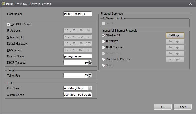
- Logging onto the camera.
- From the main menu bar, select Sensor ->Network Settings.
-
Select EtherNet/IP in the Industrial Ethernet Protocols section:
- Select the enabled Settings button next to the EtherNet/IP selection.
-
Check the Enable User Data Bypass checkbox.
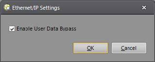
- Restart the vision system.
EtherNet/IP Functions
These functions are used to send and receive data between the In-Sight Explorer spreadsheet and the EtherNet/IP stack:
EtherNet/IP Communications
The following topic provides information and steps for configuring and utilizing EtherNet/IP and In-Sight vision systems: