FindCircleDefects
FindCircleDefects converts each pixel within an annular (ring-like) region in an input image to black or white based on a user-set threshold, with white indicating non-circular or non-radial features. The user defines and positions the annulus over the image, and chooses whether the function calculates pixel gradient in either a circular or radial direction. Values equal to or exceeding the threshold level are displayed as white pixels in the black-and-white output image.
FindCircleDefects Inputs
Syntax: FindCircleDefects(Image,Fixture.Row,Fixture.Columm,Fixture.Theta,Annulus.X,Annulus.Y,Annulus.Inner Radius,Annulus.Outer Radius,Defect Type,Deviation,Accept Thresh,Show)
| Parameter | Description | ||||||||
|---|---|---|---|---|---|---|---|---|---|
|
Specifies a reference to a spreadsheet cell that contains an Image data structure; by default, this parameter references A0, the cell containing the AcquireImage Image data structure. This parameter can also reference other Image data structures, such as those returned by the Vision Tool Image functions or Coordinate Transforms Functions. |
|||||||||
|
|
Defines the Region of Interest (ROI) relative to a Fixture input or the output of a Vision Tool function's image coordinate system. Setting the ROI relative to a Fixture ensures that if the Fixture is rotated or translated, the ROI will be rotated or translated in relation to the Fixture. For more information, see Fixture and Vision Tools. The default setting is (0,0,0), the top leftmost corner of the image.
|
||||||||
|
Also known as the Region of Interest (ROI), specifies the region of the image that undergoes analysis; creates an annular image region that can be translated and rotated. With this parameter selected, by pressing the Maximize Region button on the property sheet's toolbar, the region will automatically be stretched to cover the entire image.
|
|||||||||
|
Note: The Fixture
and Annulus parameters must be defined
within the bounds of the image; otherwise, the function will return #ERR.
|
|||||||||
|
Specifies the type of defect to which the function is sensitive: circular or radial. Pixels that vary in greyscale value from surrounding pixels indicate possible defects.
|
|||||||||
|
Specifies the degree of tolerance in the defect detection.
|
|||||||||
|
Specifies the defect threshold, in greyscale value. (0–255; default = 30) |
|||||||||
|
Specifies which graphical overlays are displayed on top of the image.
|
|||||||||
FindCircleDefects Outputs
|
Returns |
An Image data structure that stores the black-and-white ("binary") image, or #ERR if any of the input parameters are invalid. |
|
Results |
When FindCircleDefects is initially inserted into a cell, a result table is created in the spreadsheet. |
FindCircleDefects Vision Data Access Functions
The following Vision Data Access functions are automatically inserted into the spreadsheet to create the result table. For more information, see Image.
|
DarkCount |
GetDarkPixelCount(Image) |
Returns the number of pixels below the defect threshold; the pixels are displayed as black. |
|
BrightCount |
GetBrightPixelCount(Image) |
Returns the number of pixels equal to or above the defect threshold; the pixels are displayed as white. |
Additional data elements can be accessed using the following Vision Data Access function:
|
Area |
GetArea(Image) |
Returns the area of the region. |
FindCircleDefects Example
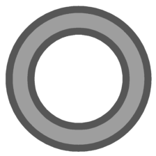
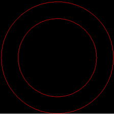
In this example, the synthetic circular (left) and radial (right) objects shown below are used to demonstrate FindCircleDefect's functionality. Both objects are medium-grey in color and feature thick, dark inner and outer borders.

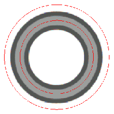
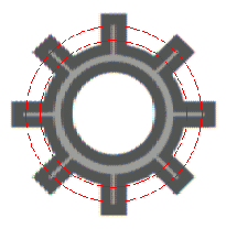
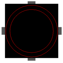
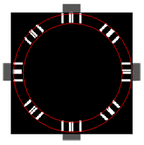
After inserting the function into the In-Sight spreadsheet, the user defines the annulus by double-clicking on the word "Annulus" in the property sheet, which disappears to reveal the red annulus overlaid on the image. The user moves or resizes the annulus using the cursor, and clicks the OK  button on the Job
Edit toolbar to confirm the selection and return to the property sheet. (The selection can also be confirmed by pressing the Enter key or by double-clicking within the annulus.) Below are images of the objects with their annuli.
button on the Job
Edit toolbar to confirm the selection and return to the property sheet. (The selection can also be confirmed by pressing the Enter key or by double-clicking within the annulus.) Below are images of the objects with their annuli.
Selecting a defect type (non-circular or non-radial), choosing "On" or "Off" for the deviation tolerance, accepting the default settings of the other parameters and clicking OKin the property sheet completes the configuration for this example and applies the function to the input image.
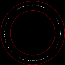
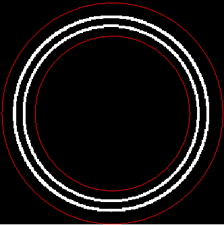
Below are black-and-white output images of the circular object, with the function set to detect non-circulardefects, the Accept Thresh parameter at the default value of 30 and the deviation tolerance at "Off" (left) and "On" (right). Notice how much stricter the "Off" setting (left) is, marking pixels in the outer edge of the circular object as possible defects, even though they appear to be part of the smooth circular curve.
Below is a black-and-white output image of the same circular object with the function now set to detect non-radialdefects. The function marks the inner and outer edges of the outer border as possible radial defects.
Below are black-and-white output images of the radial object, with the function set to detect non-radialdefects, the Accept Thresh parameter at 70 and the deviation tolerance at "Off" (left) and "On" (right). Again, notice how much stricter the "Off" setting (left) is, marking the outer edges of the radial features as possible defects.
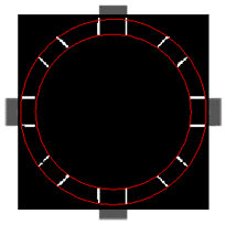
Below is a black-and-white output image of the same radial object with the tool now set to detect non-circulardefects. The function marks all radial features within the annulus as possible circular defects.
In a real-world application, the user would next reference another tool to the output image, so that a decision could be made regarding the results.
For more information, see Image.