NeighborFilter
A multipurpose function, NeighborFilter produces a greyscale output image where every pixel is the result of a "local" image-enhancement technique—for example, shrinking, expanding, filling, smoothing or edge enhancement—applied to a set of adjacent pixels ("neighbors") in the input image or region of interest (ROI). The set of pixels is called the "processing neighborhood" and is rectangular in shape, with its height and width defined by the Number of Rows and Number of Columns parameters, respectively. Many of the NeighborFilter operations process (or morph) features in the processing neighborhood based on characteristics of their shape.
- This function is only available on In-Sight vision systems running In-Sight firmware 4.x.x, and is not available on In-Sight vision systems running In-Sight firmware 5.1.0 and later. For a complete list of models and supported firmware versions, see Firmware Versions.
- In-Sight vision systems running In-Sight firmware 5.1.0 and later have had this function consolidated into the Filter function. For more information, see Filter.
- If attempting to load a job containing the PointFilter or NeighborFilter functions to an In-Sight vision system running In-Sight 5.1.x firmware, and the function is password-protected using the Format Cells dialog’s Protection tab, the job load will fail. Load the job to an In-Sight vision system running In-Sight firmware 4.x.x and modify the job. For more information on accessing or removing password-protected cells, see Licensing.
NeighborFilter Inputs
Syntax: NeighborFilter(Image,Fixture.Row,Fixture.Column,Fixture.Theta,Region.X,Region.Y,Region.High,Region.Wide,Region.Angle,Operation,Number of Rows,Number of Columns,Show)
| Parameter | Description | ||||||||||||||||||||||||||||||
|---|---|---|---|---|---|---|---|---|---|---|---|---|---|---|---|---|---|---|---|---|---|---|---|---|---|---|---|---|---|---|---|
|
This parameter must reference a spreadsheet cell that contains an Image data structure. By default, this parameter references A0, the cell containing the AcquireImage Image data structure. This parameter can also reference other Image data structures, such as those returned by the Vision Tool Image functions. For more information, see AcquireImage and Image. |
|||||||||||||||||||||||||||||||
|
Defines the Region of Interest (ROI) relative to a Fixture input or the output of a Vision Tool function's image coordinate system. Setting the ROI relative to a Fixture ensures that if the Fixture is rotated or translated, the ROI will be rotated or translated in relation to the Fixture. For more information, see Fixture and Vision Tools. Note: The default setting is (0,0,0), the top leftmost
corner of the image.
|
|||||||||||||||||||||||||||||||
|
Also known as the Region of Interest (ROI), specifies the region of the image that undergoes analysis and creates a rectangular image region that can be transformed and rotated. For more information, see Interactive Graphics Mode. Tip: With this parameter
selected, you can press the Maximize
Region button on the property sheet's toolbar to maximize the region and cover the entire image.
|
|||||||||||||||||||||||||||||||
|
Specifies the operation to perform on the processing neighborhood; the result is displayed in a greyscale output image. Some of the operations enhance edges, which are areas in an image where pixel greyscale values change sharply.
|
|||||||||||||||||||||||||||||||
|
Specifies the height (1–25; default = 3) of the processing neighborhood. Note: When Convolution is selected as the Operation,
Number of Rows is used to define the height of the kernel, in pixels.
|
|||||||||||||||||||||||||||||||
|
Specifies the width (1–25; default = 3) of the processing neighborhood. Note: When Convolution is selected as the Operation,
Number of Columns is used to define the width of the kernel, in pixels.
|
|||||||||||||||||||||||||||||||
|
Specifies which graphical overlays are displayed on top of the image.
|
NeighborFilter Outputs
|
Returns |
An Image data structure containing the processed image, or #ERR if any of the input parameters are invalid. Note: The contents
of the processed image region in the Image data structure are not saved with the job.
|
NeighborFilter Example
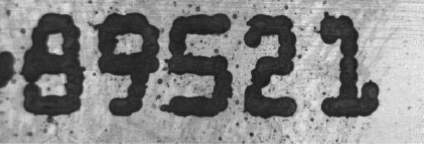
In this example, the goal is to use the Dilate operation of NeighborFilter to remove black specks surrounding a sequence of five numbers in the input image (below).
After inserting NeighborFilter into the spreadsheet, the user defines the ROI by double-clicking on the word "Region" in the property sheet, which disappears to reveal the red ROI box overlaid on the image. The user moves or resizes the box using the cursor, and clicks the OK  button on the Job
Edit toolbar to confirm the selection and return to the property sheet. (The selection can also be confirmed by pressing the Enter key or by double-clicking within the ROI.)
button on the Job
Edit toolbar to confirm the selection and return to the property sheet. (The selection can also be confirmed by pressing the Enter key or by double-clicking within the ROI.)
Selecting "Dilate" from the Operation pull-down menu, accepting the default settings of the other parameters and clicking OK in the property sheet completes the configuration for this example and applies the function to the input image.
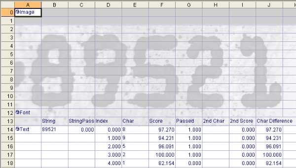
In the two images below, both the original input image and the new output image are referenced by the OCV/OCR tool, which "verifies" the numbers and displays a score for each number that indicates its confidence in the result. For more information, see OCV/OCR.
In the original input image (no dilation), the maximum OCV/OCR score is 100.000 (for the number "2") and the minimum is 82.154 (for the number "1"). The number "1" is below OCV's default Accept Threshold of 90, and the text string fails the verification.
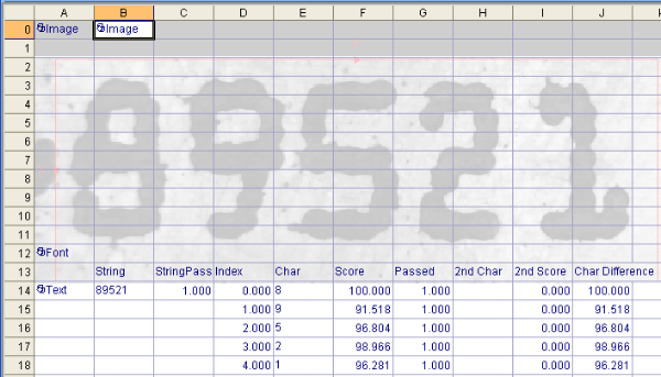
In the new output image (dilation applied), many of the black specks are removed from around the numbers and the numbers are easier to read. The maximum OCV/OCR score is 100.000 (for the number "8"), and the minimum is 91.518 (for the number "9"). All of the numbers are above OCV's default threshold of 90, and the text string passes the verification.
If the numbers are too thin, an "Erode" operation can be applied to shrink bright features and increase dark features.
For more information, see Image.