ScaleImage
ScaleImage resamples the pixels in an input image or region of interest (ROI) to produce a reduced, enlarged, unrotated or unbent version of the image. The function displays the resampled image in the upper-left corner of the In-Sight spreadsheet.
ScaleImage Inputs
Syntax: ScaleImage(Image,Fixture.Row,Fixture.Column,Fixture.Theta,Region.X,Region.Y,Region.High,Region.Wide,Region.Angle,Region.Curve,Sample Type,Sample Ratio.X Ratio,Sample Ratio.Y Ratio,Display Row,Display Column,Show)
| Parameter | Description | ||||||||||||
|---|---|---|---|---|---|---|---|---|---|---|---|---|---|
|
This parameter must reference a spreadsheet cell that contains an Image data structure. By default, this parameter references A0, the cell containing the AcquireImage Image data structure. This parameter can also reference other Image data structures, such as those returned by the Vision Tool Image functions. For more information, see AcquireImage and Image. |
|||||||||||||
|
Defines the Region of Interest (ROI) relative to a Fixture input or the output of a Vision Tool function's image coordinate system. Setting the ROI relative to a Fixture ensures that if the Fixture is rotated or translated, the ROI will be rotated or translated in relation to the Fixture. For more information, see Fixture and Vision Tools. The default setting is (0,0,0), the top leftmost corner of the image.
|
|||||||||||||
|
Also known as the Region of Interest (ROI), specifies the region of the image that undergoes analysis and creates a rectangular image region that can be transformed and rotated. For more information, see Interactive Graphics Mode. Tip: With this parameter
selected, you can press the Maximize
Region button on the property sheet's toolbar to maximize the region and cover the entire image.
|
|||||||||||||
|
Specifies the pixel-resampling technique.
|
|||||||||||||
|
|
Specifies the sample ratio in the (X,Y) direction of the region. Note: Values between
100 and 1000
specify upsampling. For example, if both the ratios are specified as 200,
the resampled image will be twice as large as the specified Region.
|
||||||||||||
|
Specifies the Row coordinate (default = 0) where the rescaled image will be displayed, relative to the upper left-hand corner. Note:
|
|||||||||||||
|
Specifies the Column coordinate (default = 0) where the rescaled image will be displayed, relative to the upper left-hand corner. |
|||||||||||||
|
Specifies which graphical overlays are displayed on top of the image.
|
ScaleImage Outputs
|
Returns |
An Image data structure containing the processed image, or #ERR if any of the input parameters are invalid. |
ScaleImage Example
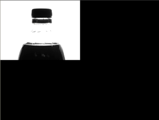
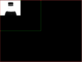
In this example, the object in the input image is a bottle. The purpose of this example is to scale the size of the bottle to 50%.

After inserting the function into the In-Sight spreadsheet, the user defines the ROI by double-clicking on the word "Region" in the property sheet, which disappears to reveal the red ROI box overlaid on the image. The user moves or resizes the box using the cursor, and clicks the OK  button on the Job
Edit toolbar to confirm the selection and return to the property sheet. (The selection can also be confirmed by pressing the Enter key or by double-clicking within the ROI.)
Typing "50" in both the X Scale and Y Scale fields, accepting the default settings of the other parameters and clicking OK in the property sheet completes the configuration for this example and applies the function to the input image.
Below is a 50% scaled image of the bottle.

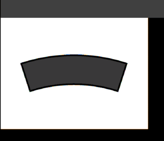
The user can also use ScaleImage to "unbend" or "unrotate" objects, which can make it easier to reference other tools to the processed output image. In this example, the object is a slightly curved segment, which is shown with the Overlay removed (achieved by clicking Overlay on the View menu). The segment will also be scaled to 50% in size, so that both the input image and output image can easily fit in the same view.

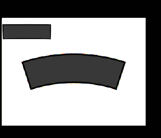
After inserting the function, defining the ROI and specifying "50" in both the X Scale and Y Scale fields in the property sheet (described earlier in the bottle example), the user incrementally changes the values in the Angle and Curve fields under the Region parameter until the object is straight. Accepting the default settings of the other parameters and clicking OK in the property sheet completes the configuration for this example and applies the function to the input image. Below is an image of the bent object in the middle and the smaller and "unbent" version in the upper-left corner.

In this example, an angle of 17.390 and a curve of -36.389 were needed to straighten the curved segment.