WriteWaveformClocked
Requests data to be clocked out one bit at a time, using one discrete output as a clock and a second output for the data, and produces a Waveform data structure containing the clocked data.
- This function is enabled only when the vision system is Online.
- When transitioning between Online and Offline states, any currently executing Waveform function will be stopped immediately, and all queued Waveforms will be dropped. The Waveforms will only begin when the In-Sight vision system is Online.
- After the function is triggered to begin the Waveform, the Waveform will continue in the background until it completes its cycle.
WriteWaveformClocked Inputs
Syntax: WriteWaveformClocked(Event,Clock Output,Data Output,Clock Period,Data Valid Edge,Queuing,Idle Periods,Bits)
| Parameter | Description | ||||
|---|---|---|---|---|---|
|
Specifies the event on which to begin the waveform. This parameter must be a reference to one of the following:
Note: When the default
Event reference is deleted, the value is replaced by a checkbox. If another
cell is referenced as an event, the function will conditionally run based
on the referenced cell. If the checkbox is enabled, the function will
always run when any inputs to the function are updated.
|
|||||
|
Specifies the output line to be used as the clock. Any discrete output line may be used, e.g. high-speed, an In-Sight vision system's user-configurable LEDs or additional I/O module outputs (if connected). Note:
|
|||||
|
Specifies the output line to be used to send the bit stream. Any discrete output line may be used, e.g. high-speed, an In-Sight vision system's user-configurable LEDs or additional I/O module outputs (if connected). Note:
|
|||||
| Clock Period | Specifies the period of time (in milliseconds) for each clock output cycle (10 to 10000; default = 1000). The duty cycle for the WriteWaveformClocked function is always 50%; i.e. the clock spends the same amount of time high and low. | ||||
| Data Valid Edge |
Specifies whether or not the next bit should be read on the rising or falling edge of the clock.
|
||||
| Queuing |
Specifies whether or not Waveform queuing is enabled or disabled.
|
||||
| Specifies the number of periods (0 to 10000; default = 3) that the function waits in the idle state after the Waveform has completed before beginning the next Waveform. | |||||
| Bits | Specifies a reference to a BitStream data structure returned by a BitStream function, which contains the bits to be sent. No more than 253 bits can be specified in the BitStream function. For more information, see BitStream. |
WriteWaveformClocked Outputs
|
Returns |
A Waveform data structure containing the clocked data; or #ERR if either input parameter is invalid. |
WriteWaveformClocked Examples
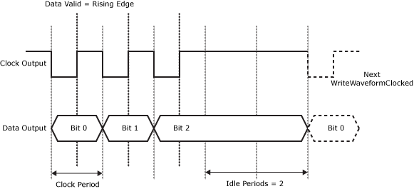
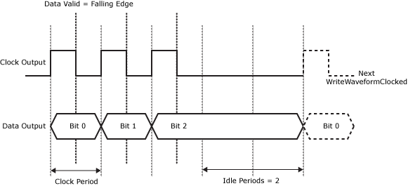
The following figures illustrate the parameters of the WriteWaveformClocked function. In each example, there are three (3) data bits and two (2) idle periods.
-
WriteWaveformClocked Function with Data Valid Edge set to Falling Edge:
-
WriteWaveformClocked Function with Data Valid Edge set to Rising Edge: