5600 and 5700 Series Vision System Ethernet Cable Specifications
The Ethernet cable is used to connect the vision system to other network devices. The Ethernet cable can be connected to a single device or provide connections to multiple devices via a network switch or router.
|
|||
|---|---|---|---|
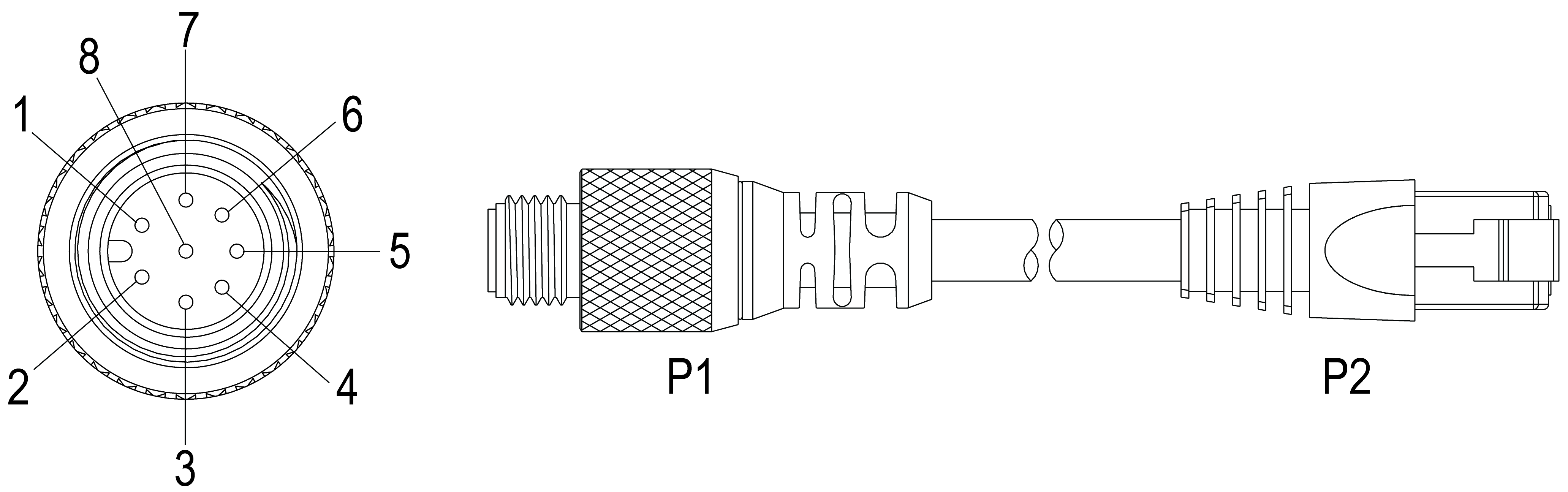
| P1 Pin# | Signal Name | Wire Color | P2 Pin# |
| 6 | MX0+ | White/Orange | 1 |
| 4 | MX0- | Orange | 2 |
| 5 | MX1+ | White/Green | 3 |
| 7 | MX2+ | Blue | 4 |
| 1 | MX2- | White/Blue | 5 |
| 8 | MX1- | Green | 6 |
| 2 | MX3+ | White/Brown | 7 |
| 3 | MX3- | Brown | 8 |
Note:
- Cables are sold separately.
- The wiring for this cable follows the TIA-568 specifications.
- To ensure reliable communication for Gigabit operation, the Ethernet cable must not exceed 75 meters (from the vision system to the endpoint). Cognex cables or patch cables should not exceed 5 meters and HCC (plenum wiring) should not exceed 60 meters. It's not recommended to use a 30 meter cable when using 1000 BaseT operation.
- A switch and a 10 meter cable can be used when experiencing issues. The wiring of the switch and cable should follow the TIA-568 specifications.