Remove the Illumination Accessory PCB
If the illumination accessory (ISLM-7000-WHI) must be uninstalled from the vision system, complete the following steps to safely remove the PCB and avoid damage to the vision system.
- Remove power from the vision system.
-
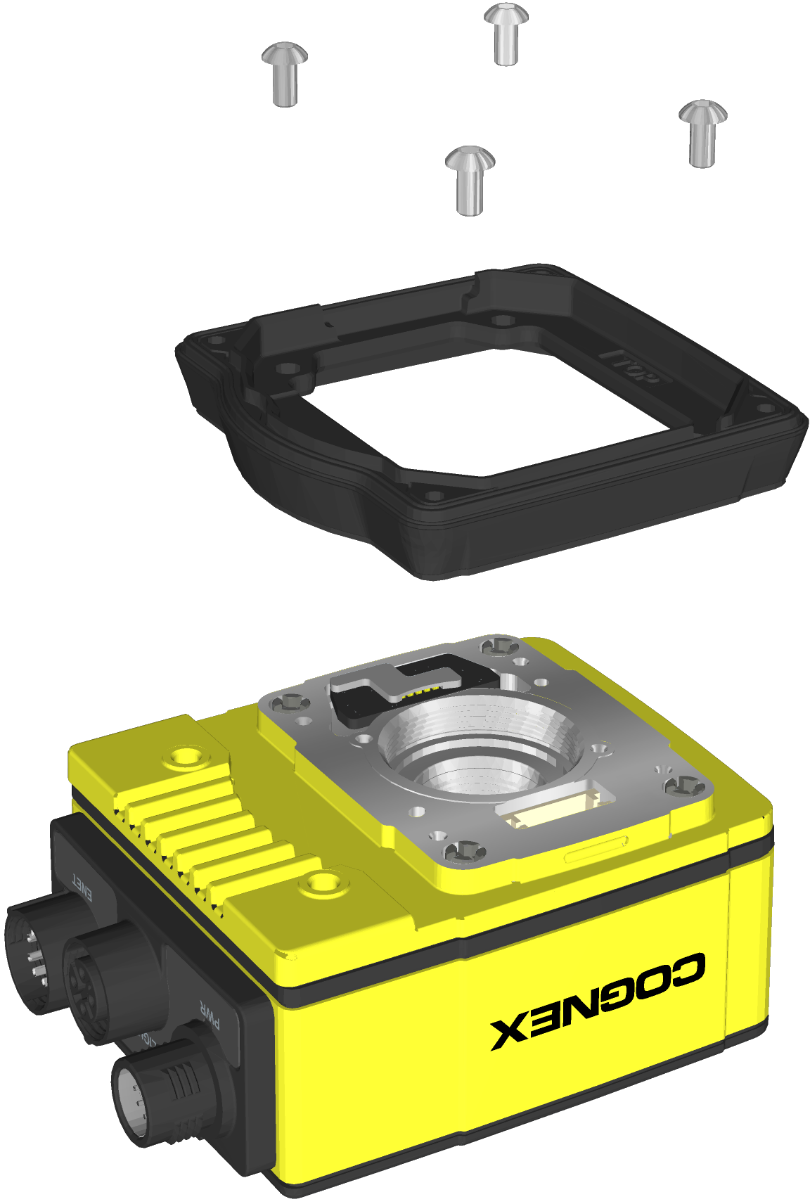
Use a 2mm hex wrench to remove the four spacer screws. Remove the spacer.
-
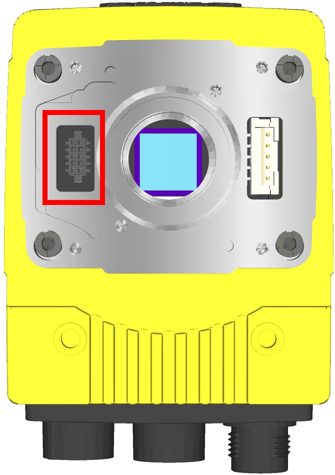
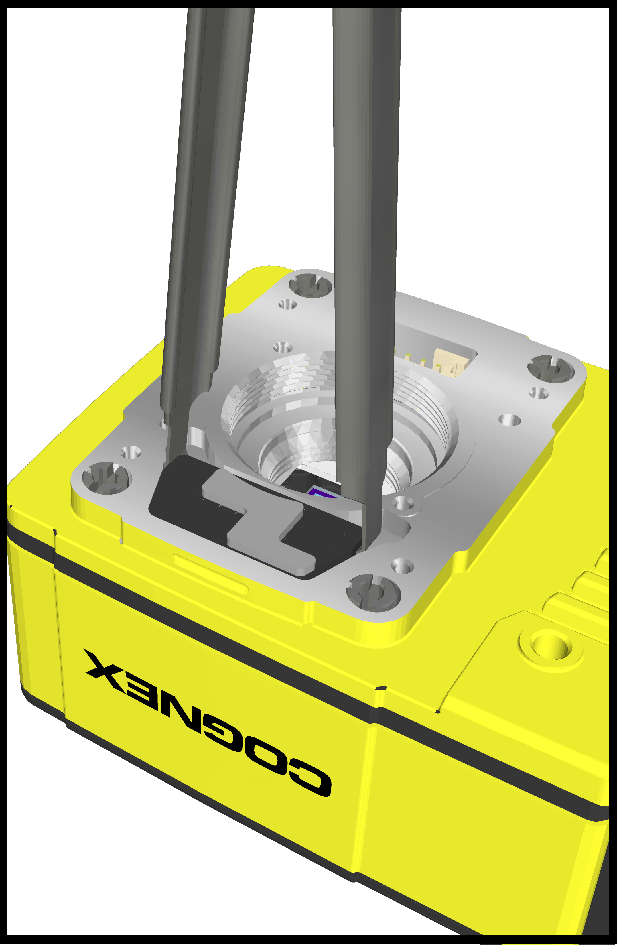
The vision system faceplate includes two lift points on either side of the PCB. Position an insulated extractor tool (for example, Jonard Tools S-340 DIP/IC Extractor) under the edges of the PCB.
-
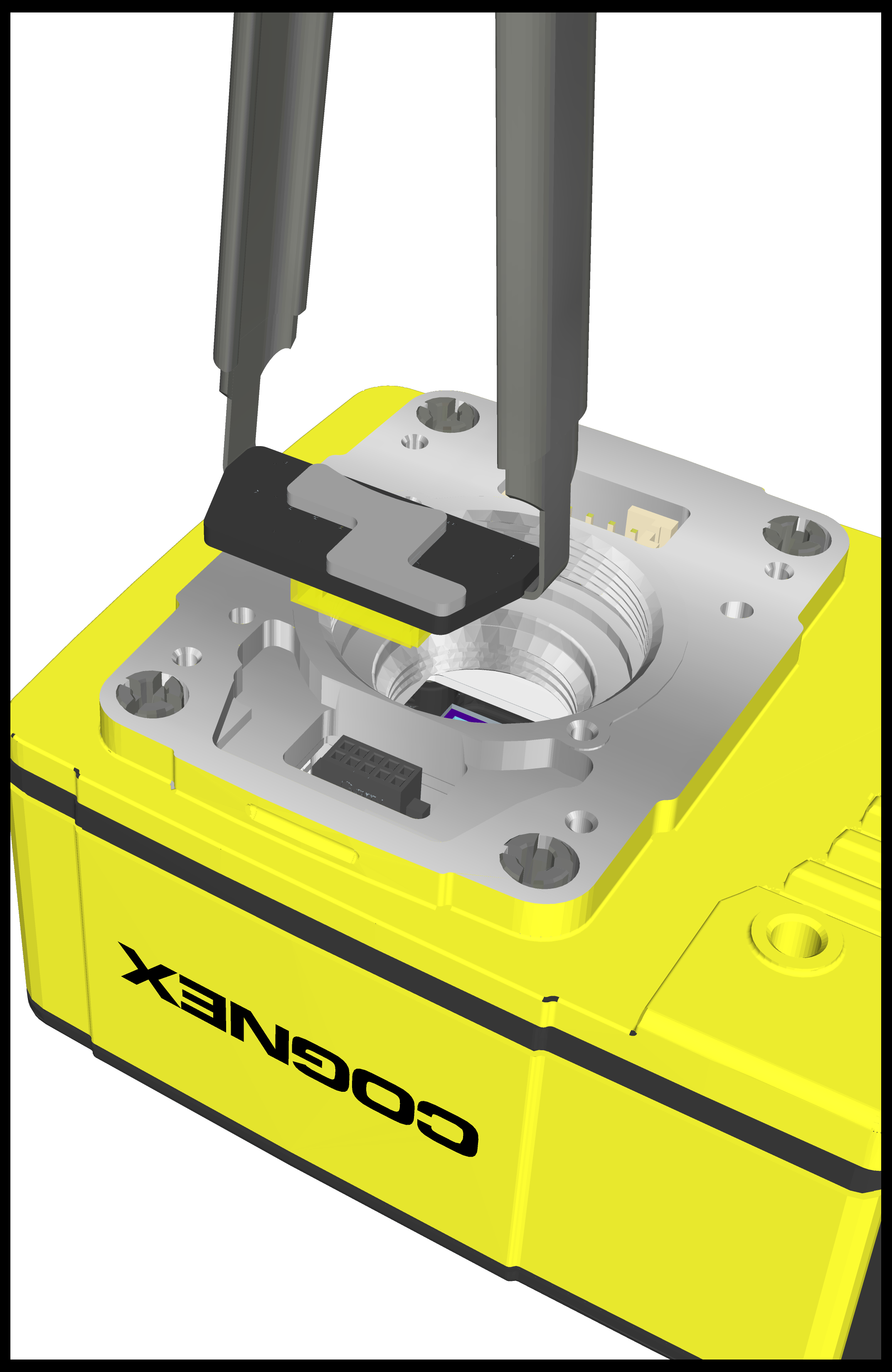
Once the extractor is engaged under the edges of the PCB, gently pull upward to disengage the PCB from the internal connector and remove the PCB.
-
Verify the removal process did not damage mating components.