Establish the Connection Using the Add-On Profile, with Keying Disabled
This topic covers how to establish a connection using the Add-On Profile with keying disabled for an In-Sight vision system running 4.10.x firmware.
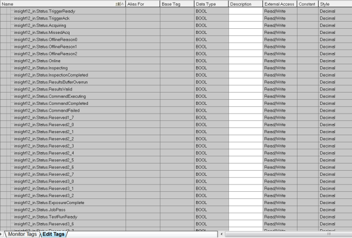
In-Sight Explorer includes the InSight_12_CopyRung.L5X import file, which can be used to copy PLC controller tag data to/from user-friendly program tags, representing signals in the In-Sight vision system running In-Sight 4.10.x firmware with TestRun. The import file defines a User Defined data type that contains both the existing Add-On Profile (AOP) signals and the new TestRun signals.
-
Open RSLogix 5000 and load the PLC's project.
Note: The PLC must be Offline to add connections in RSLogix 5000. -
Add a connection to your Ethernet Communications Card. Under the I/O Configuration node, select the Ethernet Node under the Ethernet Module, right-click on the icon and select New Module from the menu.
-
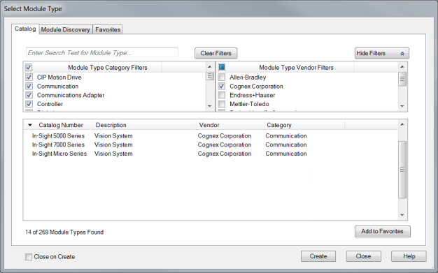
From the Select Module Type dialog, select the type of In-Sight vision system that will be connected to the PLC and click the Create button.
-
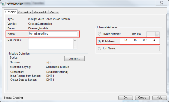
In the New Module dialog, enter the In-Sight vision system's name and IP Address and click the Change... button.
-
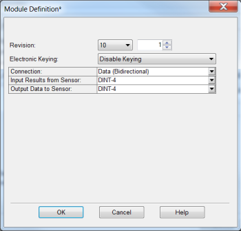
In the Module Definition dialog, select Revision 10 and select Disable Keying. Click OK.
-
After adding the vision system to the RSLogix project, the L5X rung import file can be used to create structured data for the connection. Within the main program, right-click on an empty rung and select the Import Rungs... option. Navigate to the InSight_12_CopyRung.L5X file and click the Import... button.
Note: The InSight_12_CopyRung.L5X file is installed to the following location: C:\Program Files (x86)\Cognex\In-Sight\In-Sight Explorer 5.x.x\Factory Protocol Description\RSLogix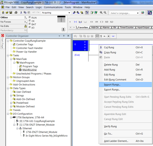
-
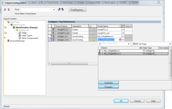
In the Import Configuration dialog, select Tags and change the names of the created tags to match the configuration. Set the InSight_12:I and InSight_12:O tags to the connection controller tags in the project so that they match the name given to the In-Sight vision system connection.
-
Click the OK button of the Import Configuration dialog to close it. A rung will be added to the project, which includes the copy instructions for copying the data between the generic connection data and the structured data types included in the imported rung file.
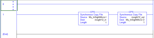
When writing your ladder program, reference the elements in the structured data variables; the copy rung above will automatically move the data to and from the structured data instances to the EtherNet/IP connection. It is important to note that the newly added camera module data will exist in Controller Tags. The User Defined data instances will exist in the Program Tags. You should write your ladder program only referencing the User Defined data instances in Program Tags. Download and run to get the tags to copy data initially, otherwise an array of SINTS will be all that is seen.