Set Region: EasyBuilder View
Sets a region contained in a symbolic tag, such as an EasyBuilder Location or Inspection Tool's region. The tool's region must contain an edit region control from an EditRegion function.
Set Region Inputs
Syntax: SR["Symbolic Tag"][Space][Row][Space][Col][Space][High][Space][Wide][Space][Angle][Space][Curve]
| Parameter | Description |
|---|---|
| "Symbolic Tag" |
The name of the Location or Inspection Tool ("Edge_1.Region", for example). |
| Space | A blank space to separate the "name" from the floating-point value. |
| Row | The x-offset of the origin, in image coordinates. |
| Space | A blank space to separate the value from the next value. |
| Col | The y-offset of the origin, in image coordinates. |
| Space | A blank space to separate the value from the next value. |
| High | The dimension along the region's x-axis. |
| Space | A blank space to separate the value from the next value. |
| Wide | The dimension along the region's y-axis. |
| Space | A blank space to separate the value from the next value. |
| Angle | The orientation, in image coordinates. |
| Space | A blank space to separate the value from the next value. |
|
Curve |
The angular deviation between the region's x-axis and the opposing boundary line. |
Set Region Outputs
Returns a status code. The status codes are:
| Status Codes | Description |
|---|---|
| 1 |
The command was executed successfully. |
| 0 |
Unrecognized command. |
| -1 |
The "Symbolic Tag" is invalid. |
| -2 |
The command could not be executed because the "Symbolic Tag" does not contain an edit region control, or the edit region control was not created by the EditRegion function. |
| -6 |
User does not have Full Access to execute the command. For more information, see User Access Settings Dialog. |
Set Region Example
You can set the Region of an EasyBuilder Location or Inspection Tool by sending a Set Region command containing the new region's position, dimensions, orientation and shape.
-
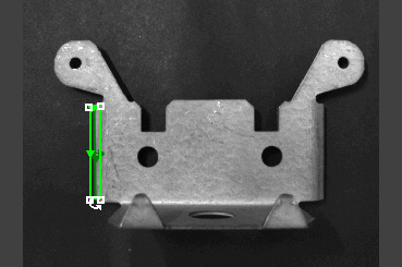
Assume that your job contains an Edge Location Tool, and the tool's region is currently in another position, with different dimensions, orientation and shape.
-
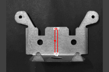
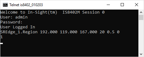
However, you would like to move and re-orient the tool's region settings via the Set Region Native Mode command. Issue the command SREdge_1.Region 192.000 119.000 167.000 20 0.5 0 as shown in the following telnet client window:
-
The In-Sight vision system responds with 1,indicating that the command was successfully executed.