AcquireImage
The AcquireImage function specifies the parameters for capturing a digital image and transferring it to the In-Sight vision system's processing memory.
In-Sight vision systems capture all images using asynchronous reset and progressive scan. Greyscale vision systems produce 8-bit images, while color vision systems produce 24-bit images. The image acquisition process begins within approximately 250µs for all vision systems, and proceeds as follows:
- The image sensor integrates light for the duration of time specified by the Exposure parameter.
- The image accumulated in the image sensor is transferred, row-by-row, into a serial shift register.
-
For every row transfer, the sensor clocks the shift register, pixel-by-pixel, out of the image sensor through the following path:
video amplifier -> Gain and Offset -> analog-to-digital converter -> vision processor memory
- The transfer begins at the specified Start Row and proceeds for the specified Number of Rows.
The memory buffer containing the acquired image is represented in the spreadsheet as an Image data structure. The Image data structure returned by AcquireImage is in turn referenced by other In-Sight spreadsheet functions that process image regions. Any function that directly or indirectly depends on acquired image data is forced to update when a new image is acquired. This relationship between the input image and other functions in the spreadsheet is what drives the execution of vision tasks on In-Sight vision systems. For more information on dependencies and cell execution order, see Spreadsheet Cell Execution and Editing Reference.
Unlike other spreadsheet functions, AcquireImage exists permanently in cell A0 and cannot be cut, copied, or cleared from the spreadsheet. This enforcement guarantees that an image is always available in a predefined location. Most Vision Tool functions, as well as many other functions, take advantage of this by specifying an absolute reference to cell A0 as their default image source. For more information, see Cell References - Relative/Absolute.
- The default AcquireImage parameter settings vary based on the vision system model. If a job is developed on one model and then loaded onto a different model, verify that the parameter settings are appropriately configured.
- If the AcquireImage function's parameters are modified programmatically, when the function displays the result of the modified parameter depends on the selected Trigger parameter.
- If the Trigger parameter is set to Camera, the AcquireImage function's parameters are loaded just after the acquisition. For example, if the function's Max Exposure value is programmatically adjusted, the change is not visible in the next image, but is available in the image after that.
- For all other Trigger parameter modes, the parameter values are loaded when the acquire signal is received, so modifications are reflected in the next image.
- When you open the AcquireImage property sheet, the vision system acquires a new image and it is displayed. If you click the Cancel button to exit the property sheet, the new image and any changes made in the property sheet are retained. If the previous image needs to be retained, save the image before you open the AcquireImage property sheet and then reload the image after opening the AcquireImage property sheet.
- If you are connected to an In-Sight Emulator and want to view images from an In-Sight vision system that had acquired images with the partial acquisition parameters (Start Row and Number of Rows) enabled, set the Start Row and Number of Rows parameters of the Emulator to the same settings as those on the In-Sight vision system that acquired the images.
- If a vision system running In-Sight 5.x.x firmware is power-cycled and no Ethernet connection is detected, it may result in missed triggers until the 30-second network timeout is complete and the vision system has fully restarted.
- If using a color In-Sight vision system:
- White Balancing is often employed as a method to equalize colors to compensate for differing lighting conditions. White balancing generates a histogram of the Red, Green, and Blue (RGB) channels of a 100x100 region in the center of the image. The peak response for each channel is found. The two channels with the lowest bin numbers are then divided into the highest bin number to get scale factors that are used to create color tables. These tables are referenced each time an image is acquired.
- The white balance settings are stored with the job and take effect once the first image is acquired by that job (not upon job load). A white field image (such as a blank piece of paper) must be acquired before entering the AcquireImage property sheet. Also ensure that the lens aperture is adjusted so that the image is not approaching saturation where all bin values are 255). Pressing the White Balance button is the same as executing the WhiteBalance function in the spreadsheet.
AcquireImage Inputs
Syntax: AcquireImage(Trigger,Manual,Exposure,Auto Exposure.Mode,Auto Exposure.Max Exposure,Auto Exposure.Target Brightness,Auto Expose Region.X,Auto Expose Region.Y,Auto Expose Region.High,Auto Expose Region.Wide,Start Row,Number of Rows,Number of Lines,Light Control.Mode,Light Control.Light Enable 0,Light Control.Light Enable 1,Light Control.Unused,Light Control.Unused,Gain,Offset,Orientation,Network Trigger.Master,Network Trigger.Master Name,Network Trigger.Master Data,Buffer Mode,Delay,Focus Metric Region.X,Focus Metric Region.Y,Focus Metric Region.High,Focus Metric Region.Angle,Focus Metric Region.Curve,White Balance Region.X,White Balance Region.Y,White Balance Region.High,White Balance Region.Wide,Line Scan.Line Trigger Type,Line Scan.Line Period/Steps Per Line,Line Scan.Encoder Acquisition Timeout,Line Scan.Clip Mode,Line Scan.Acquisition Duration,Trigger Debounce,High Dynamic Range)
| Parameter | Description | ||||||||||||||||||||||||||||||||||||||||||||||||||||||||||||||||||||||||||||||||||||||||||||||||||||||
|---|---|---|---|---|---|---|---|---|---|---|---|---|---|---|---|---|---|---|---|---|---|---|---|---|---|---|---|---|---|---|---|---|---|---|---|---|---|---|---|---|---|---|---|---|---|---|---|---|---|---|---|---|---|---|---|---|---|---|---|---|---|---|---|---|---|---|---|---|---|---|---|---|---|---|---|---|---|---|---|---|---|---|---|---|---|---|---|---|---|---|---|---|---|---|---|---|---|---|---|---|---|---|---|
|
Specifies the source of the image acquisition trigger when the In-Sight vision system is Online. Note: Do not change the Trigger programmatically while the sensor is Online. Doing so may put the sensor in an unpredictable state.
|
|||||||||||||||||||||||||||||||||||||||||||||||||||||||||||||||||||||||||||||||||||||||||||||||||||||||
|
Enables a manual image acquisition trigger when the In-Sight vision system is Offline.
|
|||||||||||||||||||||||||||||||||||||||||||||||||||||||||||||||||||||||||||||||||||||||||||||||||||||||
|
Specifies the exposure time (in milliseconds). When the vision system receives a trigger signal, light is integrated in the image sensor array for the specified duration. Shorter durations are better for stopping motion but may require larger lens apertures or higher amplifier Gain to achieve sufficient image intensity. Note:
The exposure times for In-Sight vision system models are shown in the following table. Note:
|
|||||||||||||||||||||||||||||||||||||||||||||||||||||||||||||||||||||||||||||||||||||||||||||||||||||||
|
Specifies whether the exposure time is automatically determined or not. When enabled, the exposure is automatically adjusted to compensate for different lighting conditions. Note: If the vision system does not support this feature, the parameter is disabled.
|
|||||||||||||||||||||||||||||||||||||||||||||||||||||||||||||||||||||||||||||||||||||||||||||||||||||||
|
Specifies the Region to use when automatically calculating the exposure time. Note: If the vision system does not support this feature, the parameter is disabled.
|
|||||||||||||||||||||||||||||||||||||||||||||||||||||||||||||||||||||||||||||||||||||||||||||||||||||||
|
Specifies the first row to be transferred from the image sensor into memory on the In-Sight vision system:
Note:
|
|||||||||||||||||||||||||||||||||||||||||||||||||||||||||||||||||||||||||||||||||||||||||||||||||||||||
|
Specifies the number of image sensor rows to be transferred into memory on the In-Sight vision system.
Note:
|
|||||||||||||||||||||||||||||||||||||||||||||||||||||||||||||||||||||||||||||||||||||||||||||||||||||||
|
(In-Sight 5604 and In-Sight 9902L only) |
Specifies the number of lines to acquire, to construct an image from the line scan vision system.
Note:
|
||||||||||||||||||||||||||||||||||||||||||||||||||||||||||||||||||||||||||||||||||||||||||||||||||||||
| (In-Sight 5000 series and 70xx - 74xx series only) |
The following parameters control LED light banks and rings. Note: For the In-Sight 70xx - 74xx series vision systems with the M12 lens configuration, the Light Control parameter is used to configure the pre-installed internal LED ring light. If connecting an external strobe device to the vision system's Light cable, use the Light Settings dialog to configure the light settings.
|
||||||||||||||||||||||||||||||||||||||||||||||||||||||||||||||||||||||||||||||||||||||||||||||||||||||
|
Specifies the gain of the amplifier stage that precedes the analog-to-digital converter.
Note: For very fine Gain adjustments when connected to an In-Sight 5604 or 9902L line scan vision system, you can manually type the Gain value in 0.25 increments.
|
|||||||||||||||||||||||||||||||||||||||||||||||||||||||||||||||||||||||||||||||||||||||||||||||||||||||
|
Specifies a DC level that is added or subtracted from the analog signal from the vision system before the analog-to-digital conversion. The Offset affects the image's brightness and darkness while maintaining the dynamic range within the image. Note: If the In-Sight 7905 vision system's Offset or Orientation parameters are modified outside the AcquireImage property sheet (i.e., a job is loaded with different parameter values or the parameters values are changed programmatically), it may result in a missed acquisition for Camera or Timestamp Trigger types or delay the start of the next acquisition by approximately 9ms for other Trigger types. Subsequent acquisitions will not experience this delay.
|
|||||||||||||||||||||||||||||||||||||||||||||||||||||||||||||||||||||||||||||||||||||||||||||||||||||||
| Orientation |
Specifies the orientation of the image.
Note:
|
||||||||||||||||||||||||||||||||||||||||||||||||||||||||||||||||||||||||||||||||||||||||||||||||||||||
|
When this checkbox is selected, the active vision system is designated as a "master" vision system on a network of vision systems. As a master system, the active vision system can generate a Network acquisition trigger for other In-Sight vision systems ("slaves") on the network.
Note:
|
|||||||||||||||||||||||||||||||||||||||||||||||||||||||||||||||||||||||||||||||||||||||||||||||||||||||
Note:
|
|||||||||||||||||||||||||||||||||||||||||||||||||||||||||||||||||||||||||||||||||||||||||||||||||||||||
|
When the active vision system is a master on the network, it can optionally send a string of alphanumeric data to the slaves that it triggers. To read the Master Data that it receives along with a network trigger, the slave must have a GetString function in its spreadsheet that references the AcquireImage function in cell A0. |
|||||||||||||||||||||||||||||||||||||||||||||||||||||||||||||||||||||||||||||||||||||||||||||||||||||||
| Buffer Mode |
Specifies the number of buffers used for image acquisition. The Buffer Mode parameter cannot be modified while the sensor is Online.
|
||||||||||||||||||||||||||||||||||||||||||||||||||||||||||||||||||||||||||||||||||||||||||||||||||||||
| Delay |
Note:
|
||||||||||||||||||||||||||||||||||||||||||||||||||||||||||||||||||||||||||||||||||||||||||||||||||||||
|
Specifies the Region to use when automatically calculating the Focus Metric score while in Live Video mode. Note: For the In-Sight 7000 series vision system, the Focus Metric Region is used to define the region for either calculating the autofocus of the lens or setting the focal position of the lens while in Live Video.
|
|||||||||||||||||||||||||||||||||||||||||||||||||||||||||||||||||||||||||||||||||||||||||||||||||||||||
| White Balance Region |
Specifies the Region to use when calculating the White Balance. Note: The WhiteBalance function references the White Balance Region and uses the parameters of this region when calculating the white balance.
|
||||||||||||||||||||||||||||||||||||||||||||||||||||||||||||||||||||||||||||||||||||||||||||||||||||||
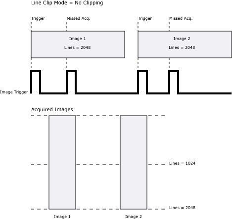
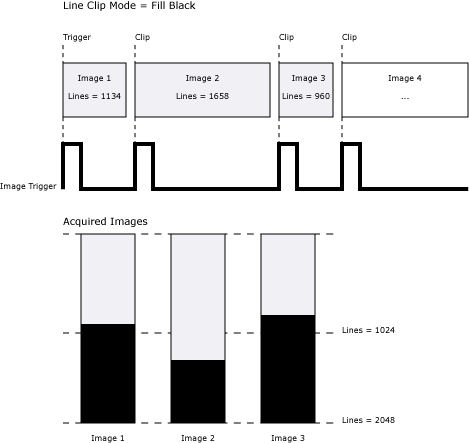
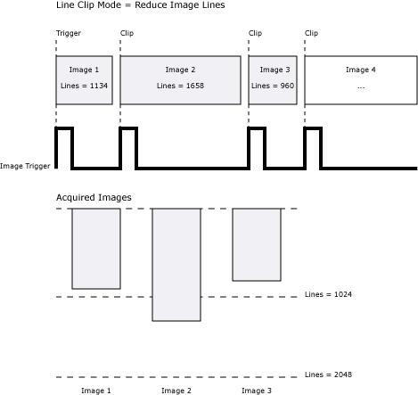
|
(In-Sight 5604 and In-Sight 9902L only) |
The Line Scan controls specify the settings of In-Sight 5604 and In-Sight 9902L line scan vision systems. The line scan vision system assembles an image row by row as the target object passes beneath it, which allows for the construction of full, "unwrapped" images of cylindrical objects or sliced, continuous images of a surface. When connected to a user-supplied hardware encoder, the line scan vision system provides high-precision images despite target speed variability. Note:
|
||||||||||||||||||||||||||||||||||||||||||||||||||||||||||||||||||||||||||||||||||||||||||||||||||||||
|
|||||||||||||||||||||||||||||||||||||||||||||||||||||||||||||||||||||||||||||||||||||||||||||||||||||||
| Trigger Debounce |
Specifies the amount of time, in microseconds, that the input trigger must remain active to be recognized as a valid trigger (0 to 65,536; default = 1). This setting delays the recognition of a valid trigger by the amount of time specified. Note:
|
||||||||||||||||||||||||||||||||||||||||||||||||||||||||||||||||||||||||||||||||||||||||||||||||||||||
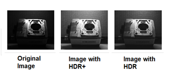
| High Dynamic Range |
HDR (High Dynamic Range) provides better contrast and more brightness for darker regions of an image. This effect is completed in a single acquisition.
Note: HDR is supported only with In-Sight 7902P, 7905 and 9912 monochrome vision systems.
The following parameters determine the HDR method and kernel size.
|
 button from the Job Display toolbar will initiate an image acquisition.
AcquireImage Outputs
The AcquireImage function returns an Image data structure. Different sensor models return different types of images.
- For the following vision systems/sensors, the resolution can be configured in the Image Settings dialog: In-Sight Micro 1500, In-Sight 2000-130, 2000-130C, 2000-230, 2000-230C, 2000-23M, 2001-230, 2001-230C, In-Sight 7500, 7600, 7600C, 7800, 7800C, 7900, 7900C, 7802, 7802C, 7902, 7902C.
- For the 5604 and 5614 line scan vision systems, the Image Height can be configured in the LineScan Settings dialog.
- For the 9902L line scan vision system, the 1K Resolution (Low Light Mode) and Max Image Height can be configured in the LineScan Settings dialog.
- Maximum frames per second is job-dependent, based on the minimum exposure for a full image frame capture using the dedicated acquisition trigger, and assumes there is no user interface connection to the vision system.
- For the In-Sight 5604 and 9902L Line Scan models, acquisition is measured in frequency (KHz).
- Functions that require an Image parameter must reference a spreadsheet cell that contains a valid Image data structure. The default Image parameter reference in all property sheets is cell A0, which contains the Image data structure returned by AcquireImage. But Image data structures returned by CompareImage, FindCircleDefects, NeighborFilter, and PointFilter are also valid references for Image Parameter values in property sheets.
| In-Sight Model | Resolution | Greyscale/Color | Bit depth | Number of grey levels or colors | FPS |
|---|---|---|---|---|---|
| Micro 1020, 1050, 1100, 1110, 1400, 1410 | 640 x 480 | greyscale | 8-bit | 256 | 60 |
| Micro 1100C and 1400C | 640 x 480 | color | 24-bit | 16,777,216 | 58 |
| Micro 1402 and 1412 | 1280 x 1024 | greyscale | 8-bit | 256 | 60 |
| Micro 1403 and 1413 | 1600 x 1200 | greyscale | 8-bit | 256 | 14 |
| Micro 1403C | 1600 x 1200 | color | 24-bit | 16,777,216 | 7 |
|
Micro 1500 |
640 x 480 | greyscale | 8-bit | 256 | 213 |
| 800 x 600 | greyscale | 8-bit | 256 | 157 | |
| 5100, 5110, 5400, 5410, 5600 | 640 x 480 | greyscale | 8-bit | 256 | 60 |
| 5100C and 5400C | 640 x 480 | color | 24-bit | 16,777,216 | 60 |
| 5604 and 5614 Line Scan | 1024 x 8192 | greyscale | 8-bit | 256 | 44 KHz |
| 5403, 5413, 5603 and 5613 | 1600 x 1200 | greyscale | 8-bit | 256 | 14 |
| 5605, 5615, 5705 and 5715 | 48 x 2048 | greyscale | 8-bit | 256 | 16 |
| 5705C | 2448 x 2048 | color | 24-bit | 16,777,216 | 14 |
| 7010, 7020, 7050, 7200, 7210, 7230, 7400, 7410, 7430 | 800 x 600 | greyscale | 8-bit | 256 | 102 |
| 7010C, 7200C, 7400C |
800 x 600 | color | 24-bit | 16,777,216 | 50 |
| 7402, 7412, 7432 | 1280 x 1024 | greyscale | 8-bit | 256 | 60 |
| 7402C | 1280 x 1024 | color | 24-bit | 16,777,216 | 30 |
|
7500, 7600, 7800, 7900 |
800 x 600 | greyscale | 8-bit | 256 | 165 |
| 640 x 480 | greyscale | 8-bit | 256 | 217 | |
|
7600C, 7800C, 7900C |
800 x 600 | color | 24-bit | 16,777,216 | 100 |
| 640 x 480 | color | 24-bit | 16,777,216 | 135 | |
| 7501, 7801, 7901 | 1280 x 1024 | greyscale | 8-bit | 256 | 76 |
| 7801C, 7901C | 1280 x 1024 | color | 24-bit | 16,777,216 | 45 |
|
7802, 7902 |
1600 x 1200 | greyscale | 8-bit | 256 | 53 |
| 800 x 600 (Low Light Mode) | greyscale | 8-bit | 256 | 53 | |
|
7802C, 7902C |
1600 x 1200 | color | 24-bit | 16,777,216 | 33 |
| 800 x 600 (Low Light Mode) | color | 24-bit | 16,777,216 | 45 | |
| 7902P | 1920 x 1200 | greyscale | 8-bit | 256 | 55 |
| 7905 | 2448 x 2048 | greyscale | 8-bit | 256 | 32 |
| 7905C | 2448 x 2048 | color | 24-bit | 16,777,216 | 17 |
| 8200 | 640 x 480 | greyscale | 8-bit | 256 | 217 |
| 8200C | 640 x 480 | color | 24-bit | 16,777,216 | 135 |
| 8400 | 640 x 480 | greyscale | 8-bit | 256 | 217 |
| 8400C | 640 x 480 | color | 24-bit | 16,777,216 | 135 |
| 8401 | 1280 x 1024 | greyscale | 8-bit | 256 | 76 |
| 8401C | 1280 x 1024 | color | 24-bit | 16,777,216 | 45 |
| 8402 | 1600 x 1200 | greyscale | 8-bit | 256 | 53 |
| 8402C | 1600 x 1200 | color | 24-bit | 16,777,216 | 33 |
| 8405 | 2592 x 1944 | greyscale | 8-bit | 256 | 13 |
|
9902L |
2048 x 16384 | greyscale | 8-bit | 256 | 66 KHz |
| 1024 x 16384 | |||||
| 9912 | 4096 x 3000 | greyscale | 8-bit | 256 | 14 |
| 9912C | 4096 x 3000 | color | 24-bit | 16,777,216 | 8 |