Robot Communications - FANUC Robot Controller
Overview
The purpose of this topic is to outline the steps to connect and transfer data from an In-Sight vision system to a FANUC Robot Controller. For this topic, the robot controller will be the device controlling the acquisition and transfer of data. In general, the robot controller, with the use of In-Sight Native Mode commands, will trigger the vision system to acquire and process an image and then the robot controller will request specific data from the vision system. Data can be transferred using serial or Ethernet communications.
Serial Communications
This section provides instructions for establishing communication between a FANUC robot controller and an In-Sight vision system over a serial connection.
Requirements
Required Hardware
- In-Sight vision system (In-Sight Micro 1000 series, In-Sight 5000 series, In-Sight 7000 series or the In-Sight 8000 series vision system)
- For serial communications, an I/O module, Breakout cable (In-Sight 5000 series or In-Sight 7000 series only).Note:
- While serial-based robot communications are supported with the Breakout cable (In-Sight 5000 series or In-Sight 7000 series only), an I/O module is recommended for ease of setup.
- In-Sight Micro 1000 series vision systems only support serial communication when connected to the CIO-MICRO or CIO-MICRO-CC I/O module.
- There are two options for enabling serial communication for the In-Sight 70xx - 74xx series vision system: using the Breakout cable or using the CIO-MICRO or CIO-MICRO-CC I/O module. When connected to the Breakout cable (and there is no connection to an I/O module), the vision system allows one discrete input line and one discrete output line to be configured as Serial Receive and Serial Transmit, respectively.
- In-Sight 8000 series vision systems only support serial communication when connected to the CIO-MICRO I/O module.
- The CIO-WENET Ethernet I/O module does not support serial communication.
- DB9 Serial Cable
- Computer
- FANUC Robot Controller (RJ2 or RJ3)
- K-Floppy Cable (DB25 to DB9)
- Null Modem Adapter (DB9 to DB9)
Required Software
- Cognex In-Sight Explorer version 3.3 or higher
- Cognex In-Sight Explorer firmware version 3.3 or higher
- FANUC KAREL® programming language
KAREL Robot Controller Code
VAR
  file_var     :FILE
  Status       :STRING[4]
  xs           :STRING[9]
  ys           :STRING[9]
  angles       :STRING[9]
  x            :REAL
  y            :REAL
  angle        :REAL

BEGIN
-- Connect to In-Sight
OPEN FILE file_var ('RW', 'P2:')

-- Instruction In-Sight to Acquire an Image
-- (wait for a response)
WRITE file_var ('sw8',CHR(13))

-- Read status
READ file_var (status::1::0)
IF status <> '1' THEN
  WRITE TPDISPLAY('sw8 Failed',CR)
  RETURN
ENDIF

CLR_IO_STAT(file_var)

-- Get the value in cell C7
WRITE file_var ('gvc007',CHR(13))

-- Read status
READ file_var (status::1::0)
IF status <> '1' THEN
  WRITE TPDISPLAY('gvc007 Failed',CR)
  RETURN
ENDIF

CLR_IO_STAT(file_var)

-- Read the data
-- This will split the information at the quotations "'".
-- Example String '10.5''9.8''15.9'
READ file_var (xs::0::2, ys::0::2, angles::0::2, CR)

-- Convert the data
CNV_STR_REAL(xs, x)
CNV_STR_REAL(ys, y)
CNV_STR_REAL(angles, angle)

-- Remove comment for testing
-- WRITE TPDISPLAY('X:',x,CR,'Y:',y,CR,'R',Angle,CR)

--
-- Use Vision Data
--

-- Close the connection
CLOSE FILE file_var
In-Sight Serial Port Setup
While connected to the vision system (with the vision system Offline):
-
On the Sensor menu, click Serial Port Settings.
-
Click the I/O Module button to open the I/O Module Configuration dialog and configure the I/O module. Press the OK button to close the I/O Module Configuration dialog and return to the Serial Port Settings dialog.
Note: If the vision system is configured for use with the CIO-MICRO or CIO-MICRO-CC I/O module, the RS-232 TRANSMIT and RS-232 RECEIVE pins on the Breakout cable are disabled. Use the I/O module's RS-232 OUT port (DB9) to connect to a serial device.Set the following properties in the Serial Port Settings dialog:
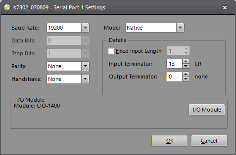
- Baud Rate: 19200
- Data Bits: 8 (set by default when using the CIO-1400)
- Stop Bits: 1 (set by default when using the CIO-1400)
- Parity: None
- Handshake: None
- Mode: Native
- Fixed Input Length: Disabled
- Input Terminator: 13
- Output Terminator: 0
- Verify that the dialog displays the "(attached)" message next to the I/O module that is physically attached to the vision system.
- Click OK.
In-Sight Job Setup
- From the File menu, create a New Job.
- In the AcquireImage property sheet (double-click on cell A0), set the following parameters:
- Trigger = External
- Manual = Checked
- Select cell A2 and type ExtractBlobs and press Enter (at this point the ExtractBlobs property sheet will be displayed).
- Click OK (leaving all parameters at their default settings).
- Select cell A4 and, fromthe Palette's Snippets tab, insert the Communication > Robots > FANUC.cxd Snippet into the spreadsheet.
- Define the coordinate cell references:
- X: Double-click C6, double-click C2,
- Y: Double-click D6, double-click D2
- Angle: Double-click E6, double-click E2
- Press the Manual Trigger icon a few times to confirm that data from the ExtractBlobs function is changing.
- Save the job.
- Put the vision system Online.
Ethernet Communications
This section covers the two options for configuring communication between a FANUC robot controller and an In-Sight vision system over Ethernet communications.
TCP/IP
This section covers how to configure communication between a FANUC robot controller and an In-Sight vision system over TCP/IP.
Requirements
Required Hardware
- In-Sight vision system (In-Sight Micro 1000 series, In-Sight 5000 series, In-Sight 7000 series or the In-Sight 8000 series vision system)
- Ethernet Cable
- Computer
- FANUC Robot Controller (RJ2 or RJ3)
Required Software
- Cognex In-Sight Explorer version 3.3 or higher
- Cognex In-Sight Explorer firmware version 3.3 or higher
- FANUC KAREL programming language
KAREL Robot Controller Setup
Configuring the Socket Messaging Option
The tag you want to setup cannot be configured for use by another device on your network.
- Cold start the controller.
- On the teach pendant , press and hold the SHIFT and RESET keys. Or, on the operator panel , press and hold RESET.
- While still pressing SHIFT and RESET on the teach pendant (or RESET on the operator panel), press the ON button on the operator.
- Release all keys.
- On the teach pendant, press MENUS.
- Select SETUP.
- Press F1, [TYPE].
- Select Host Comm.
- Press F4, [SHOW].
- Choose Clients.
-
Move the cursor to the tag you want set up for Socket Messaging, and press F3.You will see a screen similar to the following:
SETUP Tags
Tag C3: ****************
1 Comment: SM
2 Protocol name: *****
3 Port name: *************************
4 Mode: UNDEFINED
Current ********
State: ****************************
5 Remote: 192.168.0.1
6 Path: ****************************
Startup OFF
7 State: 15 min
8 Remote: 9 Path: Options 10 Error Reporting: 11 Inactivity Timeout: - Move the cursor to Protocol name, and press F4, [CHOICE].
- Select SM.
- Move the cursor to StartupState, and press F4, [CHOICE].
- Select Start, and press ENTER.
- Select Remote, and press ENTER.
- Type in the of the remote host server you want to use for socket messaging, and press F2, [ACTION].
-
Select DEFINE.
Note: If you are not using DNS, you must add the remote host and its IP address into the host entry table.
Set the System Variable (Client Tag)
- Press MENUS.
- Select NEXT.
- Select SYSTEM, and press F1, [TYPE].
- Select Variables.
- Move the cursor to $HOSTC_CFG, and press ENTER.
-
Move the cursor to the structure corresponding to the tag selected in the previous section, Set up the Tag.For example, if you are setting up tag S3, move the cursor structure element [3], as shown in the following screen.
SYSTEM Variables $HOSTS_CFG 1 [1] HOST_CFG_T 2 [2] HOST_CFG_T 3 [3] HOST_CFG_T 4 [4] HOST_CFG_T 5 [5] HOST_CFG_T 6 [6] HOST_CFG_T 7 [7] HOST_CFG_T 8 [8] HOST_CFG_T -
Press ENTER.You will see a screen similar to the following.
SYSTEM Variables $HOSTS_CFG[3] 1 $COMMENT *uninit* 2 $PROTOCOL 'SM' 3 $PORT *uninit* 4 $OPER 3 5 $STATE 3 6 $MODE *uninit* 7 $REMOTE *uninit* 8 $REPERRS FALSE 9 $TIMEOUT 15 10 $PATH *uninit* 11 $STRT_PATH *uninit* 12 $STRT_REMOTE *uninit* 13 $USERNAME *uninit* 14 $PWRD_TIMOUT 0 15 $SERVER_PORT 23 - Move the cursor to $SERVER_PORT.Type in the name of the TCP/IP server port you want to use for socket messaging.
- The client tag is now ready to use from a KAREL program.
KAREL Robot Controller Code
The code example shows the controller connecting to an In-Sight vision system with IP address 192.168.0.1; To find the IP address of your vision system, from In-Sight Explorer, right-click the vision system name in the In-Sight Network pane and select Properties.
PROGRAM eComm
VAR
  file_var : FILE
  tmp_int  : INTEGER
  mp_str   : STRING[128]
  status   : INTEGER
  entry    : INTEGER
  try      : INTEGER
  statuss      :STRING[1]
  xs           :STRING[9]
  ys           :STRING[9]
  angles       :STRING[9]
  x            :REAL
  y            :REAL
  angle        :REAL
BEGIN
  WRITE TPDISPLAY(CR,CR,CR,CR,CR,CR,CR,CR,CR,CR,CR,CR,CR,CR,CR)
  SET_FILE_ATR(file_var, ATR_IA)

  -- Connect the tag
  WRITE TPDISPLAY('Connecting...',CR)
  MSG_DISCO('C3:', status)
  MSG_CONNECT('C3:',status)
  OPEN FILE file_var('rw','C3:')

  -- Read the In-Sight Welcome message
  WRITE TPDISPLAY('Logging In',CR)
  mp_str =''
  READ file_var(mp_str)
  WRITE TPDISPLAY(mp_str,CR)

  -- Read User: prompt
  READ file_var(mp_str::6::0)
  IF UNINIT(mp_str) THEN
    mp_str = ''
  ENDIF
  WRITE TPDISPLAY(mp_str,CR)
  IF (mp_str <>'User: ') THEN
    WRITE TPDISPLAY('User Failed',CR)
    --Error
    RETURN
  ENDIF

  --Send User Name
  WRITE file_var('admin',CHR(13),CHR(10))

  -- Read Password prompt
  mp_str =''
  READ file_var(mp_str::10::0)
  IF UNINIT(mp_str) THEN
    mp_str = ''
  ENDIF
  WRITE TPDISPLAY(mp_str,CR)
  IF (mp_str <>'Password: ') THEN
    WRITE TPDISPLAY('Password Failed',CR)
    --Error
    RETURN
  ENDIF

  --Send Password
  WRITE file_var('',CHR(13),CHR(10))

  -- Read Login Response
  mp_str =''
  READ file_var(mp_str)
  IF UNINIT(mp_str) THEN
    mp_str = ''
  ENDIF
  WRITE TPDISPLAY(mp_str,CR)
  IF (mp_str <> 'User Logged In') THEN
    WRITE TPDISPLAY('Log In Failed',CR)
    --Error
    RETURN
  ENDIF

  -- Instruction In-Sight to Acquire an Image
  -- (wait for a response)
  WRITE TPDISPLAY('Trigger',CR)
  WRITE file_var ('sw8',CHR(13),CHR(10))

  -- Read Status
  READ file_var (statuss)
  IF statuss <> '1' THEN
    WRITE TPDISPLAY('sw8 Failed',CR)
    RETURN
  ENDIF

  -- Get the value in cell C7
  WRITE TPDISPLAY('Get Value C7',CR)
  WRITE file_var ('gvc007',CHR(13),CHR(10))

  -- Read Status
  READ file_var (statuss)
  IF statuss <> '1' THEN
    WRITE TPDISPLAY('gvc007 Failed',CR)
    RETURN
  ENDIF

  -- Read the data
  -- This will split the information at the quotations "'".
  -- Example String '10.5''9.8''15.9'
  READ file_var (xs::0::2, ys::0::2, angles::0::2, CR)

  --Disconnect Socket
  MSG_DISCO('C3:', status)

  -- Convert the data
  CNV_STR_REAL(xs, x)
  CNV_STR_REAL(ys, y)
  CNV_STR_REAL(angles, angle)
  WRITE TPDISPLAY('X:',x,CR,'Y:',y,CR,'R',Angle,CR)
END eComm
In-Sight Job Setup
- From the File menu, create a New Job.
- In the AcquireImage property sheet (double-click on cell A0), set the following parameters:
- Trigger = External
- Manual = Checked
- Select cell A2 and type ExtractBlobs and press Enter (at this point the ExtractBlobs property sheet will be displayed).
- Click OK (leaving all parameters at their default settings).
- Select cell A4 and, from the Palette's Snippets tab, insert the Communication > Robots > FANUC Communications Snippet into the spreadsheet.
- Define the coordinate cell references:
- X: Double-click C6, double-click C2,
- Y: Double-click D6, double-click D2
- Angle: Double-click E6, double-click E2
- Press the Manual Trigger icon a few times to confirm that data from the ExtractBlobs function is changing.
- Save the job.
- Put the vision system Online.
EtherNet/IP
This section covers how to configure communication between a FANUC robot controller and an In-Sight vision system over EtherNet/IP (EIP). In this example setup scenario, the robot controller will be the device that controls the acquisition and subsequent transfer of data from the vision system. In general, the robot controller will trigger the vision system to acquire and process an image for X, Y and angle data. EtherNet/IP communications will be used to trigger the vision system and send data to the robot controller, while 16-bit digital input lines will be used to transfer the 2D part location.
- Negative floating point numbers cannot be sent over input lines, all numbers will be multiplied by 10 by the vision system, and subsequently divided by 10 by the robot controller.
- The I/O configuration used in this section is an example, and the actual I/O configuration may vary. EtherNet/IP uses rack 89, though slot placement may vary by installation; this example uses rack 89 and slot 1.
Requirements
Required Hardware
- In-Sight vision system (In-Sight Micro 1000 series, In-Sight 5000 series, In-Sight 7000 series or the In-Sight 8000 series vision system)
- Ethernet Cable
- Computer
- FANUC Robot Controller (R-30iA™)
Required Software
- In-Sight Explorer version 4.8 or higher
- In-Sight Explorer firmware version 4.8 or higher
- FANUC Software R540 EtherNet/IP I/O Scanner
- FANUC Teach Pendant Programming (TPP)
EtherNet/IP Setup
- Connect to the In-Sight vision system that will be communicating with the robot controller.
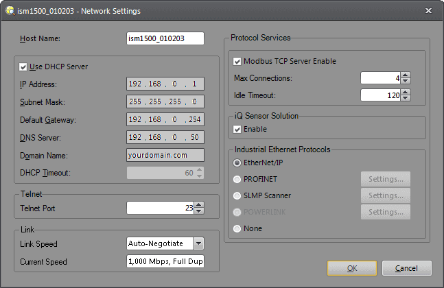
- From the Sensor menu, select Network Settings... to open the Network Settings dialog.
-
Set the Industrial Ethernet Protocols to EtherNet/IP.
TPP Robot Controller Setup
- Launch the FANUC R540 EtherNet/IP I/O Scanner software.
- Press MENU.
- Select I/O.
-
Press F1, [TYPE], and select EtherNet/IP.A screen similar to the below will be displayed:
EtherNet/IP List(Rack 89) 1/32 Description TYP Enable Status Slot Connection1 ADP FALSE OFFLINE 1 Connection2 ADP FALSE OFFLINE 2 Connection3 ADP FALSE OFFLINE 3 Connection4 ADP FALSE OFFLINE 4 Connection5 ADP FALSE OFFLINE 5 Connection6 ADP FALSE OFFLINE 6 Connection7 ADP FALSE OFFLINE 7 Connection8 ADP FALSE OFFLINE 8 Connection9 ADP FALSE OFFLINE 9 ConnectionA ADP FALSE OFFLINE 10 ConnectionB ADP FALSE OFFLINE 11 ConnectionC ADP FALSE OFFLINE 12 ConnectionD ADP FALSE OFFLINE 13 ConnectionE ADP FALSE OFFLINE 14 ConnectionF ADP FALSE OFFLINE 15 ConnectionG ADP FALSE OFFLINE 16 ConnectionH ADP FALSE OFFLINE 17 ConnectionI ADP FALSE OFFLINE 18 ConnectionJ ADP FALSE OFFLINE 19 ConnectionK ADP FALSE OFFLINE 20 -
Select the appropriate connection, rename it, and the table should then reflect the following once the system has been correctly connected:
EtherNet/IP List(Rack 89) 1/32 Description TYP Enable Status Slot COGNEX SCN TRUE RUNNING 1 Connection2 ADP FALSE OFFLINE 2
In-Sight Vision System EtherNet/IP I/O Configurations
| In-Sight Micro 1000 Series Vision Systems | In-Sight 5100, 5400 & 5600 Series Vision Systems | In-Sight 5705/5705C Vision Systems | In-Sight 70xx -74xx Series Vision Systems | In-Sight 7000 Gen2 Series Vision Systems | In-Sight 8000 Series Vision System | In-Sight 9000 Series Vision System |
|---|---|---|---|---|---|---|
|
|
|
|
|
|
|
Defining Inputs
| Name | Signal Type | Signal Label | Unit Map |
|---|---|---|---|
| DI_Trig_Ready | DI | Trigger Ready | 0 |
| DI_Trig_Ack | DI | Trigger Ack | 1 |
| DI_Acquiring | DI | Acquiring | 2 |
| DI_Miss_Ack | DI | Missed Acquisition | 3 |
| GI_Offline_Reason | GI | Offline Reason | 4-6 |
| DI_Online | DI | Online | 7 |
| DI_Inspecting | DI | Inspecting | 8 |
| DI_Inspect_Comp | DI | Inspection Completed | 9 |
| DI_Buffer_Overrun | DI | Results Buffer Overrun | 10 |
| DI_Results_Valid | DI | Results Valid | 11 |
| DI_Job_Loading | DI | Job Loading | 12 |
| DI_Load_Comp | DI | Job Load Completed | 13 |
| DI_Load_Fail | DI | Job Load Failed | 14 |
| GI_Reserved | GI | Reserved | 15-23 |
| GI_Reserved2 | GI | Reserved | 24-26 |
| DI_ExposureComp | DI | Exposure Completed | 27 |
| DI_JobPass | DI | Job Pass | 28 |
| GI_Reserved3 | GI | Reserved | 29-31 |
| GI_CurrentJobID | GI | Current Job ID | 32-47 |
| GI_AcquisitionID | GI | Ack ID | 48-64 |
| GI_InspectionID | GI | Inspection ID | 65-80 |
| GI_InspectionResult | GI | Inspection Result | 81-96 |
| GI_X_Position | GI | User Data Input 0 | 97-112 |
| GI_Y_Position | GI | User Data Input 1 | 113-128 |
| GI_Angle | GI | User Data Input 2 | 129-144 |
| DI_X_Negative | DI | 145 | |
| DI_Y_Negative | DI | 146 | |
| DI_A_Negative | DI | 147 |
Sample
Below is a sample digital input configuration for the robot controller; EtherNet/IP is Rack 89, and the Slot is the connection number from the EtherNet/IP configuration section. The bits start at 1.
| # | RANGE | RACK | SLOT | START | STATUS |
|---|---|---|---|---|---|
| 1 | DI[ 1- 80] | 0 | 0 | 0 | UNASG |
| 2 | DI[ 81- 88] | 48 | 1 | 21 | ACTIV |
| 3 | DI[ 89- 100] | 0 | 0 | 0 | UNASG |
| 4 | DI[ 101-120] | 48 | 1 | 1 | ACTIV |
| 5 | DI[ 121-124] | 89 | 1 | 1 | ACTIV |
| 6 | DI[ 125-133] | 89 | 1 | 8 | ACTIV |
| 7 | DI[ 134-585] | 89 | 1 | 145 | ACTIV |
Defining Outputs
| Name | Signal Type | Signal Label | Unit Map |
|---|---|---|---|
| DO_Trig_Enable | DO | Trigger Enable | 0 |
| DO_Trigger | DO | Trigger | 1 |
| DO_Results_Enable | DO | Buffer Results Enable | 2 |
| DO_Results_Ack | DO | Inspection Results Ack | 3 |
| DO | Reserved | 4 | |
| DO | Reserved | 5 | |
| DO | Reserved | 6 | |
| DO_Set_Offline | DO | Set Offline | 7 |
| DO_SE0 | DO | Soft Event 0 | 8 |
| DO_SE1 | DO | Soft Event 1 | 9 |
| DO_SE2 | DO | Soft Event 2 | 10 |
| DO_SE3 | DO | Soft Event 3 | 11 |
| DO_SE4 | DO | Soft Event 4 | 12 |
| DO_SE5 | DO | Soft Event 5 | 13 |
| DO_SE6 | DO | Soft Event 6 | 14 |
| DO_SE7 | DO | Soft Event 7 | 15 |
| DO_Reserved | GO | Reserved | 16-31 |
| DO_UserData_000 | GO | User Data 0 | 32-39 |
| DO_UserData_001 | GO | User Data 1 | 40-47 |
Sample
Below is a sample digital output configuration for the robot controller.
| # | RANGE | RACK | SLOT | START | STATUS |
|---|---|---|---|---|---|
| 1 | DO[ 1- 80] | 0 | 0 | 0 | UNASG |
| 2 | DO[ 81- 84] | 48 | 1 | 21 | ACTIV |
| 3 | DO[ 85- 100] | 0 | 0 | 0 | UNASG |
| 4 | DO[ 101-120] | 48 | 1 | 1 | ACTIV |
| 5 | DO[ 121-184] | 89 | 1 | 1 | ACTIV |
| 6 | DO[ 185-256] | 89 | 1 | 65 | ACTIV |
| 7 | DO[ 257-616] | 89 | 1 | 153 | ACTIV |
Group I/O Configuration
| GI# | RACK | SLOT | START PT | NUM PTS |
|---|---|---|---|---|
| 1 | 89 | 1 | 5 | 3 |
| 2 | 89 | 1 | 33 | 16 |
| 3 | 89 | 1 | 49 | 16 |
| 4 | 89 | 1 | 65 | 16 |
| 5 | 89 | 1 | 81 | 16 |
| 6 | 89 | 1 | 97 | 16 |
| 7 | 89 | 1 | 113 | 16 |
| 8 | 89 | 1 | 129 | 16 |
| # SIM VALUE | 7/64 |
|---|---|
| GI[ 1]U | 0 [GI_Offline_Reas] |
| GI[ 2]U | 56 [GI_CurrentJob_ID ] |
| GI[ 3]U | 56 [GI_Ack_ID ] |
| GI[ 4]U | 56 [GI_Inspect_ID ] |
| GI[ 5]U | 0 [GI_Inspect ] |
| GI[ 6]U | 2426 [GI_X_Position ] |
| GI[ 7]U | 3208 [GI_Y_Position ] |
| GI[ 8]U | 242 [GI_Angle ] |
TPP Robot Controller Code
The following sample code illustrates how to trigger the In-Sight vision system, get the Group input data, and the X, Y and Angle data (checking whether or not it is a negative value). The I/O values may change, depending on the robot I/O configuration.
1:  DO[121:DO_Trigger_Enable]=ON
2:  WAIT DI[121:DI_Trigger_Ready]=ON
3:  DO[122:DO_Trigger]=ON
4:
5:  WAIT DI[122:DI_Trigger_Ack]=ON
6:  DO[122:DO_Trigger]=OFF
8:
9:  IF DI[127:DI_Inspect_Complete]= OFF,JMP LBL[2]
10:
11:  LBL[1]
12:  WAIT DI[127:DI_Inspect_Complete] =OFF
13:  JMP LBL[3]
14:
15:  LBL[2]
16:  WAIT DI[127:DI_Inspect_Complete]=ON
17:
18:  LBL[3]
19:
20:  R[2:X Position]=GI[6:GI_X_Position]
21:  R[2:X Position]=R[2:X Position]/10
22:
23:  IF DI[145:X_Negative]=OFF,JMP LBL[4]
24:  R[2:X Position]=R[2:X Position]*(-1)
25:
26:  LBL[4]
27:
28:  R[3:Y Position]=GI[7:GI_Y_Position]
29:  R[3:Y Position]=R[3:Y Position]/10
30:  IF DI[146:Y_Negative]=OFF,JMP LBL[5]
31:
32:  R[3:Y Position]=R[3:Y Position]*(-1)
33:
34:  LBL[5]
35:
36:  R[4:Angle]=GI[8:GI_Angle]
37:  R[4:Angle]=R[4:Angle]/10
38:
39:  IF DI[147:A_Negative]=OFF,JMP LBL[6]
40:
41:  R[4:Angle]=R[4:Angle]*(-1)
42:
43:  LBL[6]
44:L @P[1] 50mm/sec FINE
45:
46:
47:
48:  PR[1,1]=R[2:X Position]
49:  PR[1,2]=R[3:Y Position]
50:
51:  PR[1,6]=PR[1,6]+R[4:Angle]
52:
53:L  PR[1] 50mm/sec FINE
54:  WAIT    .50(sec)
55:  PR[1,6]=47.002
56:
57:L @P[1] 100mm/sec FINE
In-Sight Vision System and Robot Controller Calibration
It is highly important to calibrate the In-Sight vision system's results from pixels into real-world measurement units, using a high-accuracy checkerboard calibration plate. This section covers important facets of the calibration process between the vision system and the robot.
When setting up the calibration, place the calibration plate in the Field of View (FOV) of the vision system. Ensure that the calibration plate fills the entire FOV of the vision system. If it is not possible to fill the entire FOV, multiple poses (e.g. multiple images must be captured) must be used.
Creating a Robot User Frame
There are two possible ways to create the robot user frame: allowing the CalibrateGrid function to assign the origin or manually assigning the origin.
CalibrateGrid Origin
The image below illustrates how the origin is automatically assigned by the CalibrateGrid function. The origin is located at the intersection of the two red crosses on the +X and +Y axis.When the robot user frame is setup in this way, the robot user frame origin (0,0) is the same as the CalibrateGrid function (0,0).

Manual Origin Assignment
The image below illustrates how the origin is assigned manually, with the origin being assigned to the bottom left corner, the +X the bottom right and the +Y the top left.The X,Y location of the green cross must be manually entered into the Pose pane of the CalibrateGrid function.

In-Sight Job Setup and Part Training
Once the In-Sight vision system has been calibrated, it is time to configure the rest of the settings to run the job.
The vision system should be configured to accept an external trigger. In EasyBuilder View, in the Set Up Image Application Step, the Trigger parameter should be set to External.
Next, use a PatMax pattern model to locate your part. In EasyBuilder View, go to the Locate Part Application Step and add a PatMax Pattern Location Tool to locate the part. Next, go to the Inspect Part Application Step and add three Math Math & Logic Tools to multiply the absolute value of X, Y and angle values and round them up. Three additional Math Math & Logic Tools should also be used to determine if the output value is negative or positive.
In-Sight Job I/O Configuration
With the tools setup and returning results, the next step is getting the results out to the robot controller. In EasyBuilder View, go the Communications Application Step. Press the Add Device button, then select Robot as the Device, FANUC as the Manufacturer, EtherNet IP Robot as the Protocol, and press the OK button. Once the device has been added, EasyBuilder will automatically search your job for any Location or Inspection Tools that define a fixture and generate a data string representing the fixture.
In the Format Output Data tab, any tool that generates a fixture will be listed in the Position Name drop-down list. If your job only contains one tool that returns positional data, it will be selected by default. Otherwise, select the tool whose output string you want to send from the Position Name drop-down list. The Output Buffer string will be displayed, as well as the Message Size in bytes, for reference purposes.
In-Sight Vision System Interface Communications
To use the Sensor Interface option a third-party protocol converter, from PREMOSYS (premosys.com), is required.This converter handles the serial handshaking protocol of FANUC's Sensor Interface.
Requirements
Required Hardware
- In-Sight vision system (In-Sight Micro 1000 series, In-Sight 5000 series, In-Sight 7000 series or the In-Sight 8000 series vision system)
- For serial communications, an I/O module, Breakout cable (In-Sight 5000 series or In-Sight 7000 series only).Note:
- There are two options for enabling serial communication for the In-Sight 70xx - 74xx series vision system: using the Breakout cable or using the CIO-MICRO or CIO-MICRO-CC I/O module. When connected to the Breakout cable (and there is no connection to an I/O module), the vision system allows one discrete input line and one discrete output line to be configured as Serial Receive and Serial Transmit, respectively.
- In-Sight Micro 1000 series vision systems only support serial communication when connected to the CIO-MICRO or CIO-MICRO-CC I/O module.
- There are two options for enabling serial communication for the In-Sight 70xx - 74xx series vision system: using the Breakout cable or using the CIO-MICRO or CIO-MICRO-CC I/O module. When connected to the Breakout cable (and there is no connection to an I/O module), the vision system allows one discrete input line and one discrete output line to be configured as Serial Receive and Serial Transmit, respectively.
- PREMOSYS Protocol converter VE0010
- Computer
- FANUC Robot Controller (RJ2 or RJ3)
- Serial Cable (DB25 to DB25)
- In-Sight to VE0010 cable (see VE0010 manual)
Required Software
- Cognex In-Sight Explorer version 3.3 or higher
- Cognex In-Sight Explorer firmware version 3.3 or higher
- FANUC Sensor Interface Option
Robot Controller Teach-Pendant Code
 1:  R[20:MEASURE_CNTR_CAM]=0    ;
   2:  R[2:ALARM CODE]=0    ;
   3:  LBL[9] ;
   4:  !REGISTER CHOICE ;
   5:  R[51:REGISTER_CHOICE]=5    ;
   6:  R[6:INTERMEDIATE_CALC]=R[51:REGISTER_CHOICE]*65536    ;
   7:  R[1:SEND_CAM]=R[50:PRODUCT_CHOICE]+256    ;
   8:  R[1:SEND_CAM]=R[1:SEND_CAM]+1    ;
   9:  R[1:SEND_CAM]=R[1:SEND_CAM]+R[6:INTERMEDIATE_CALC]    ;
  10:  R[5:REC_ACK]=0    ;
  11:  SEND R[1:SEND_CAM] ;
  12:  RCV R[5:REC_ACK] LBL[1] TIMEOUT,LBL[1] ;
  13:  R[20:MEASURE_CNTR_CAM]=R[20:MEASURE_CNTR_CAM]+1    ;
  14:  JMP LBL[2] ;
  15:  !Measurement I/O ;
  16:  LBL[2] ;
  17:  IF R[5:REC_ACK]=1,JMP LBL[3] ;
  18:  !Measurement Not OK ;
  19:  IF R[20:MEASURE_CNTR_CAM]=1,JMP LBL[9] ;
  20:  IF R[20:MEASURE_CNTR_CAM]=2,JMP LBL[10] ;
  21:  LBL[10] ;
  22:  !In-Sight TO ROBOT ;
  23:  IF R[5:REC_ACK]=2 OR R[5:REC_ACK]=3 OR R[5:REC_ACK]=6,JMP LBL[4] ;
  24:  !ROBOT TO In-Sight ;
  25:  IF R[5:REC_ACK]=4 OR R[5:REC_ACK]=5 OR R[5:REC_ACK]=8 OR
    :  R[5:REC_ACK]=9,JMP LBL[5] ;
  26:  !POSITION IS Not OK ;
  27:  IF R[5:REC_ACK]=12,JMP LBL[6] ;
  28:  LBL[4:Alarm Code 1] ;
  29:  R[2:ALARM CODE]=4    ;
  30:  JMP LBL[3] ;
  31:  LBL[5:Alarm Code 2] ;
  32:  R[2:ALARM CODE]=5    ;
  33:  JMP LBL[3] ;
  34:  LBL[6:Alarm Code 3] ;
  35:  R[2:ALARM CODE]=6    ;
  36:  JMP LBL[3] ;
  37:  LBL[3:End] ;
In-Sight Serial Port Setup
While connected to the vision system (with the vision system Offline):
- On the Sensor menu, click Serial Port Settings.
-
Set the following properties in the Serial Port Settings Dialog:
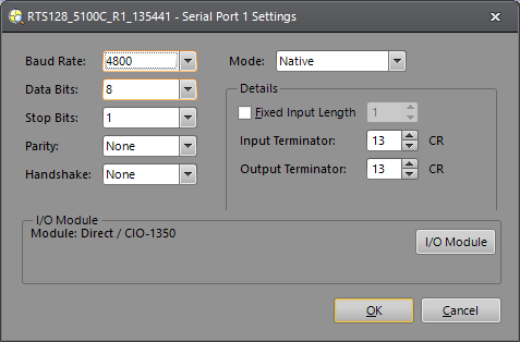
- Baud Rate: 4800
- Data Bits: 8
- Stop Bits: 1
- Parity: None
- Handshake: None
- Mode: Native
- Fixed Input Length: Unchecked
- Input Terminator: 13
- Output Terminator: 13
- Click OK.
In-Sight Job Setup
Use the sample included with the VE0010 protocol converter.
Troubleshooting
Serial with HyperTerminal
In-Sight Serial Port Setup
While connected to the vision system (with the vision system Offline):
-
On the Sensor menu, click Serial Port Settings.
-
Click the I/O Module button to open the I/O Module Configuration dialog and configure the I/O module. Press the OK button to close the I/O Module Configuration dialog and return to the Serial Port Settings dialog.
Note: If the vision system is configured for use with the CIO-MICRO or CIO-MICRO-CC I/O module, the RS-232 TRANSMIT and RS-232 RECEIVE pins on the Breakout cable are disabled. Use the I/O module's RS-232 OUT port (DB9) to connect to a serial device. -
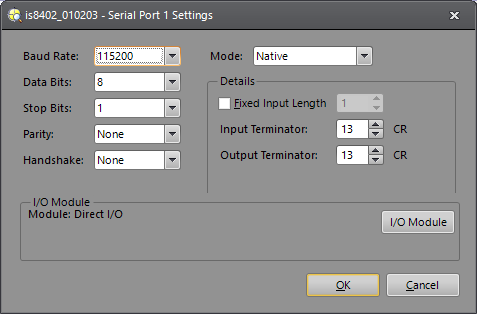
Set the following properties in the Serial Port Settings dialog:
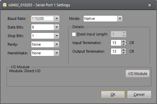
- Baud Rate: 115200
- Data Bits: 8 (set by default when using the CIO-1400)
- Stop Bits: 1 (set by default when using the CIO-1400)
- Parity: None
- Handshake: None
- Mode: Native
- Fixed Input Length: Disabled
- Input Terminator: 13
- Output Terminator: 13
- Verify that the dialog displays the "(attached)" message next to the I/O module that is physically attached to the vision system.
- Click OK.
Set Up a Test Job
- From the File menu, create a New Job.
- In the AcquireImage property sheet (double-click on cell A0), set the following parameters:
- Trigger = External
- Manual = Checked
- Select cell A2 and type ExtractBlobs and press Enter (at this point the ExtractBlobs property sheet will be displayed).
- Click OK (leaving all parameters at their default settings).
- Select cell A4 and type FindBlobs and press Enter (at this point the FindBlobs property sheet will be displayed).
- Reference cell B2 for the Blobs parameter.
- Click OK.
- Press the Manual Trigger icon a few times to confirm that data is changing.
- Put the vision system Online.
Connect to an In-Sight Vision System
- From Windows click Start > All Programs > Accessories > Communications > HyperTerminal.
- Create a New Connection (File > New Connection).
- Port: COM1
- Bits per second: 115200
- Data bits: 8
- Parity: None
- Stop bits: 1
- Flow Control: None
- Click File > Properties > Settings.
- Emulation: ANSI
- ANSII Setup (for viewing ease) set the following:
- Send line ends with line feeds
- Echo typed characters locally
- Append line feeds to incoming line ends
- Wrap lines that exceed terminal width
- Click Connect.
- Enter the vision system's user name then password (default user name is admin and the password in blank).
- You should now see "User Logged In".
- Type: SW8 and press Enter (this will cause a manual trigger and the image should change).
- Type: GVC004 and press Enter (this will get the value stored in cell C4).
Verify Ethernet Connection with Telnet
Set Up a Test Job
- From the File menu, create a New Job.
- In the AcquireImage property sheet (double-click on cell A0), set the following parameters:
- Trigger = External
- Manual = Checked
- Select cell A2 and type ExtractBlobs and press Enter (at this point the ExtractBlobs property sheet will be displayed).
- Click OK (leaving all parameters at their default settings).
- Select cell A4 and type FindBlobs and press Enter (at this point the FindBlobs property sheet will be displayed).
- Reference cell B2 for the Blobs parameter.
- Click OK.
- Press the Manual Trigger icon a few times to confirm that data is changing.
- Put the vision system Online.
Connect to an In-Sight Vision Sytem
- From Windows click Start > Run.
- In the Run window type: telnet <sensor's IP Address> (example: telnet 10.27.80.66).
- Click OK.
- Enter the vision system's user name then password (default user name is admin and the password in blank).
- You should now see "User Logged In".
- Type: SW8 and press Enter(this will cause a manual trigger and the image should change).
- Type: GVC004 and press Enter(this will get the value stored in cell C4).
- To disconnect your telnet session type CTRL + ].
- Type "quit" to close the window.