CalibrateGrid
Utilizing a user-configurable calibration grid pattern, CalibrateGrid
creates a 2D transformation to convert between pixel and real-world coordinate
systems. CalibrateGrid also accounts for linear, non-linear and lens distortion
About CalibrateGrid
CalibrateGrid computes a 2D transformation between the set of points identified by the dots found in a calibration grid-of-dots pattern, or the vertices of a checkerboard calibration grid pattern. In addition, CalibrateGrid automatically accounts for any optical or perspective distortion present in the lens being used to acquire the image.
- The type of calibration grid pattern to be used.
- The calibration grid pattern's spacing.
- The type of real-world, physical measurement units.
- The number of poses is set, from 1 to 30.
Optionally, a calibration plate grid can be printed if you don't already have one. Next, an image of the pattern is acquired, using the Pose pane. Once the image has been acquired, CalibrateGrid will automatically identify as many feature points as possible. As soon as the Calibration button is pressed, CalibrateGrid will begin to compute the calibration and report a "Calibration Score" based on the spacing of the feature points, with the results being displayed in the Results pane.
After the calibration has been performed, the calibration data is stored in the CalibrateGrid cell. This allows the CalibrateGrid function to be copied from one job and pasted to another, or exported and imported as an external file using Export Cell/Import Cell. It is possible to have a different calibration for each job, as well as multiple calibrations in a single job, if necessary. Other functions that utilize Calibrate functions as arguments can reference the CalibrateGrid data structure, as well.
- When using a Calibrate, CalibrateAdvanced or CalibrateGrid function, the physical and optical set-up (the lens, sensor and the physical relationship between the sensor and the scene being acquired) must be the same for both the calibration and run-time operation. If any of these items is altered, the system must be re-calibrated. Therefore, it is recommended that the same sensor and lens be used to both calibrate and process the run-time images. The sensor and lens must also retain their original set-up and calibration settings. For example, changing the acquisition format (by altering the resolution) or moving the sensor will invalidate the computed 2D transformation that maps pixel to real-world coordinates.
- The In-Sight 5604 line scan vision system only operates in pixel coordinates. While the Calibrate Functions may be added to a job running on an In-Sight 5604, they will produce inaccurate results.
CalibrateGrid Dialog Panes and Controls
The CalibrateGrid dialog is composed of three panes for calibration: Setup pane, Pose pane, and Results pane.
Setup Pane
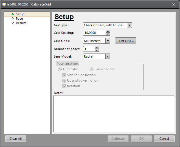
| Parameter | Description | ||||||||||||||||||||||||||
|---|---|---|---|---|---|---|---|---|---|---|---|---|---|---|---|---|---|---|---|---|---|---|---|---|---|---|---|
|
Grid Type: |
Specifies the type of calibration pattern that will be used to construct the calibration: Checkerboard, with fiducial; Checkerboard, no fiducial; Dots, with fiducial; or Dots, no fiducial.
|
||||||||||||||||||||||||||
|
Grid Spacing: |
Specifies either the size of a square in a checkerboard pattern, or the distance from center to center of the dots in a grid-of-dots pattern (.0000001 to 9999999; default = 10.00). |
||||||||||||||||||||||||||
|
Grid Units: |
Specifies the real-world measurement units (Microns, Millimeters (default), Centimeters or Inches) that the calibration will be based upon. |
||||||||||||||||||||||||||
|
Number of Poses: |
Specifies the number of poses that will be required to complete the calibration. Multiple poses are required when a single calibration pattern cannot fill the field of view. In this type of calibration, the calibration pattern is placed in various physical locations to cover the field of view. Each position of the calibration pattern is called a pose. CalibrateGrid can process between 1 and 30 poses. When more than two poses are selected, the Pose Location options will become enabled. These options are used to specify the expected movement of the calibration pattern between poses. |
||||||||||||||||||||||||||
|
Lens Model: |
Specifies the type of distortion correction (Radial or Projection; default = Radial) to use based on the type of lens being used to acquire the image. Radial refers to distortion that affects any optical lens where the magnification is different at the edges of the field of view than at the center of the field of view. Radial distortion is generally more severe with larger fields of view; wide-angle lens tend to exhibit more radial distortion than telephoto lens. Projection refers to distortion introduced when the vision system's optical axis is not perpendicular to the scene being acquired. |
||||||||||||||||||||||||||
|
Print Grid: |
Press to print the selected Grid Type. Note: The Print Grid functionality should only be used in situations of coarse
measurements and experimentation, and not in applications that require
a high degree of precision and accuracy (a precisely fabricated calibration
pattern is required for those types of applications).
|
||||||||||||||||||||||||||
|
Pose Locations - Automatic (default): |
Specifies how the CalibrateGrid function should account for more than one pose (the Number of Poses parameter must be set to a value greater than 2 to enable this option).
The Automatic mode only provides optical calibration (correcting perspective and lens distortions) for the vision system. Since the Automatic mode is used to stitch up multiple views of the calibration grid into the coordinate system of the first pose view, the real-world coordinates of the origin in Pose 1 are the only world coordinate values that must be entered. All additional poses, as long as the fiducial is found, can be calibrated without specifying the origin for each pose. |
||||||||||||||||||||||||||
|
Pose Locations - User-Specified: |
Specifies how the CalibrateGrid function should account for more than one pose (the Number of Poses parameter must be set to a value greater than 2 to enable this option).
The User-Specified mode can be used to perform hand-eye calibration, a calibration type that not only provides data for correcting perspective and lens optical distortions, but also calibrates the camera from the image coordinate space to the motion coordinate space. Since the User-Specified mode is used for multi-view calibration, the motion device pose for each view must be manually entered. |
Pose Pane
| Parameter | Description | ||||||
|---|---|---|---|---|---|---|---|
|
Origin Location (World Coordinates): |
Specifies the X and Y location of the origin in real-world coordinates; and in the event of a discrepancy between the angular relationship of the grid's axes and the real-world axes, the Angle may be specified, as well. Note: If Pose Locations is enabled in the
Setup pane, and User-Specified mode is selected, the Origin Location (World Coordinates) is actually used to specify the motion pose of the motion device instead of the position and angle of the calibration plate's origin.
|
||||||
|
Feature Points Found: |
Displays the total number of extracted feature points to be used in the calibration. | ||||||
|
Acquire Image: |
Specifies how the image will be acquired.
|
||||||
|
Grid Axes: |
Specifies the grid axes of the calibration pattern when a calibration pattern without a fiducial is selected (Checkerboard, no fiducial or Dots, no fiducial). | ||||||
|
Adjust Region: |
Launches interactive graphics mode to define a region of interest for the calibration; only features within the region of interest will be used in the calibration. | ||||||
|
Feature Points Table: |
Displays the feature points extracted from the image in their pixel row/column coordinates, as well as their calibration pattern location in grid coordinates (X,Y), relative to the origin. The X and Y coordinates are updated anytime the origin value changes. Extracted feature points are graphically displayed by a green-colored "x" at each feature location. Selecting a feature point from the table, or clicking on a feature point in the graphical display, will highlight the feature in both locations and show its coordinates graphically. |
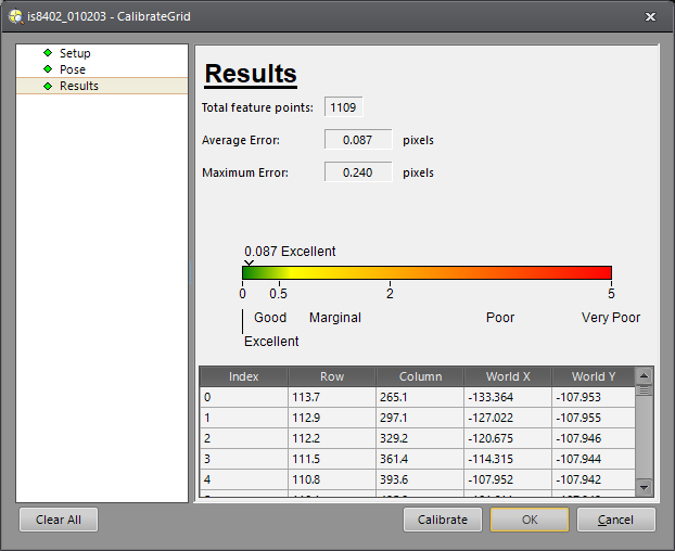
Results Pane
| Parameter | Description |
|---|---|
|
Total Feature Points: |
Displays the total number of feature points were extracted and used in the calibration. |
|
Average Error: |
Displays the average error, in pixels, during the calibration. |
|
Maximum Error: |
Displays the maximum error, in pixels, during the calibration. |
| Calibration Graphic: |
Displays a graphic representation of the calibration.
|
|
Feature Points Table: |
Displays the feature points extracted from the image in their pixel row/column coordinates, as well as their calibration pattern location in grid coordinates (X,Y), relative to the origin. The X and Y coordinates are updated anytime the origin value changes. Extracted feature points are graphically displayed by a green-colored "x" at each feature location. Selecting a feature point from the table, or clicking on a feature point in the graphical display, will highlight the feature in both locations and show its coordinates graphically. |
How To Use CalibrateGrid
Inserting a CalibrateGrid Function
- Right-click an empty cell and select Insert Function to open the Insert Function dialog.
- In the left side of the Insert Function dialog, expand the Coordinate Transforms list of tool categories.
- Select the CalibrateGrid function from the Function list and press the OK button.
Configuring the Calibration Pattern Using the Setup Pane
When a CalibrateGrid function is first inserted, the Setup pane will automatically appear.
- To begin configuring the calibration pattern, from the Grid Type parameter, select a calibration pattern.
- Set the Grid Spacing value; this is used to define either the size of a square in a checkerboard pattern, or the distance from center to center of the dots in a grid-of-dots pattern.
- Set the Grid Units, which are the real-world measurement units that the real-world coordinates will be based upon.
-
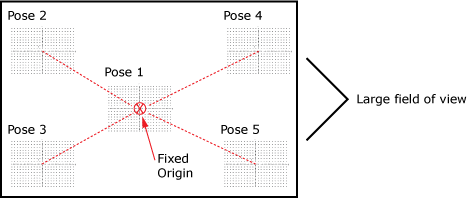
Determine the number of poses that will be necessary to complete the calibration and enter that value into the Number of poses parameter. When a single calibration pattern cannot fill the field of view, multiple calibration patterns must be used. In this type of calibration, the calibration pattern is placed in various physical locations to cover the field of view. Each position of the calibration pattern is called a pose. CalibrateGrid can process between 1 and 30 poses. When more than two poses are selected, the Pose Location options will become enabled. These options are used to specify the expected movement of the calibration pattern between poses.
The default setting is Automatic, which essentially allows for free movement of the calibration pattern. When it is selected, the real-world coordinates of the origin in Pose 1 are the only world coordinate values that need to be entered. All additional poses, as long as the fiducial is found, are calibrated without specifying the origin for each pose.
Note: The Automatic mode only provides optical calibration (correcting perspective and lens distortions) for the vision system.The User-Specified mode is selected when one wants to perform a hand-eye calibration to establish relationship to a motion device's motion coordinate system. The motion device pose for each view must be manually entered. Users do not need to determine the calibration plate's origin position, since the placement offset (in position and orientation) between the calibration plate and the motion device is unknown.
Note: The User-Specified mode provides both optical calibration and motion device calibration. - Before printing the grid pattern, select the Lens Model (Radial or Projection) to define the type of distortion correction to use based on the type of lens being used to acquire the image. Radial (the default setting) refers to distortion that affects any optical lens where the magnification is different at the edges of the field of view than at the center of the field of view. Radial distortion is generally more severe with larger fields of view; wide-angle lens tend to exhibit more radial distortion than telephoto lens. Projection refers to distortion introduced when the vision system's optical axis is not perpendicular to the scene being acquired.
Printing the Calibration Pattern Using the Print Grid Dialog
- Once the calibration pattern has been configured, click on the Print Grid button to print a copy of the calibration pattern.
- Click on the Page Setup button to configure the calibration pattern before printing, using the Page Setup dialog.
- Click on the Print button to launch the Print dialog. From here, the calibration pattern can be printed.
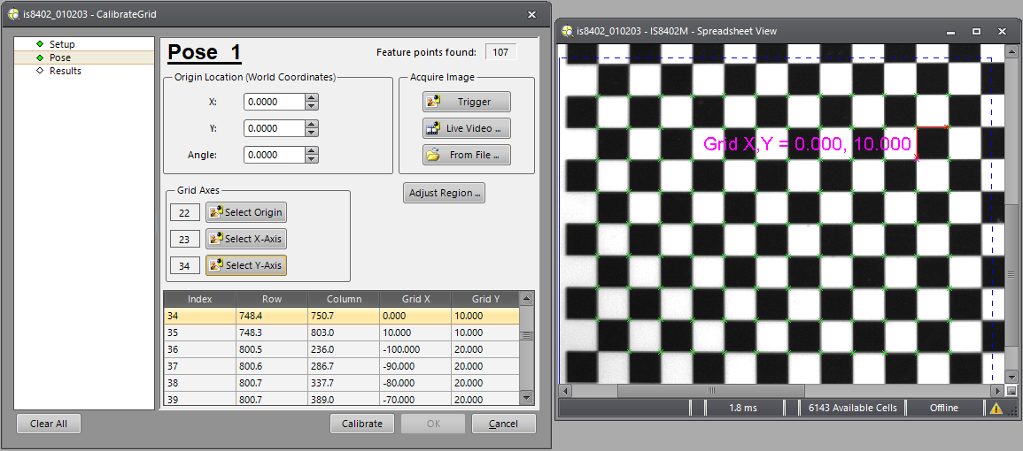
Acquiring an Image of the Calibration Pattern Using the Pose Pane
Once the calibration pattern has been configured in the Setup pane, select Pose (or Pose 1 if there are multiple poses to configure) from the navigational pane. This will display the Pose pane.
-
There are three options for acquiring an image for calibration: Trigger, Live Video, or From File.
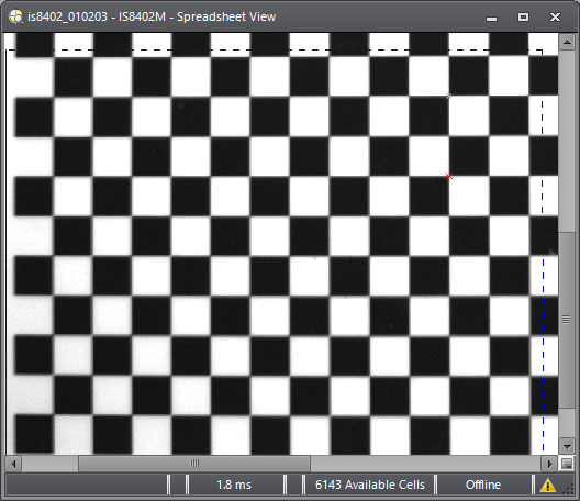
Note: The most accurate results are obtained when the calibration pattern is sharply focused across the entire field of view. Also, when processing the features, CalibrateGrid does not discriminate whether or not the features are dark-on-light or light-on-dark. -
Once the image is acquired, CalibrateGrid will automatically extract the feature points.
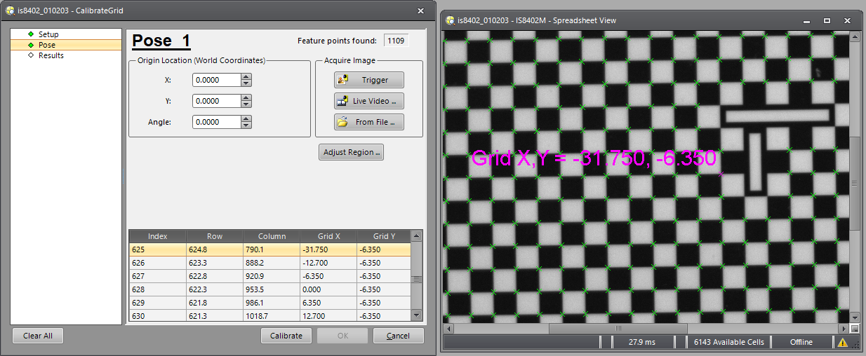
- To display the data table showing each feature extracted, press the toggle button (press it again to hide the table). The table displays the feature points extracted from the image in their pixel row/column coordinates, as well as their calibration pattern location in grid coordinates (X,Y), relative to the origin. The X and Y coordinates are updated anytime the origin value changes. Extracted feature points are graphically displayed by a green-colored "x" at each feature location. Selecting a feature point from the table, or clicking on a feature point in the graphical display, will highlight the feature in both locations and show its coordinates graphically, as shown above.
In every instance that a new image is acquired or a Pose dialog is re-entered, the region size is adjusted and the feature points will be re-extracted and the display results will also be updated. By default, the entire image is used in feature extraction. Pressing the Adjust Region button launches interactive graphics mode, where it is possible to define a region of interest and ignore the parts of the image outside of that space.
Modifying or Setting the Origin in the Pose Pane (optional)
If Pose Locations is enabled in the
Setup pane, and Automatic mode is selected, the Origin Location
field is used to specify the X and Y location of the origin in real-world
coordinates. In addition, if there is any discrepancy between the angular
relationship of the grid's axes and the real-world axes, that can be set
using the Angle box. The origin
can be altered for instances where it might be more convenient to place
the origin at the center of an object, rather than the corner of the image. The origin location of the calibration can be
altered by adjusting the X, Y and/or Angle
boxes in the Origin Location (World
Coordinates) field. The values can be increased or decreased by
clicking the  buttons, or by manually entering the desired
numeric value. When Automatic mode is selected, the real-world coordinates of the origin in Pose
1 are the only world coordinate values that need to be entered. All additional
poses, as long as the fiducial is found, are calibrated without specifying
the origin for each pose.
buttons, or by manually entering the desired
numeric value. When Automatic mode is selected, the real-world coordinates of the origin in Pose
1 are the only world coordinate values that need to be entered. All additional
poses, as long as the fiducial is found, are calibrated without specifying
the origin for each pose.
If Pose Locations is enabled in the Setup pane, and User-Specified mode is selected, the Origin Location (World Coordinates) is actually used to specify the motion pose of the motion device instead of the position and angle of the calibration plate's origin. The User-Specified mode is used to perform a hand-eye calibration to establish relationship to a motion device's motion coordinate system. The motion device pose for each view must be manually entered. Users do not need to determine the calibration plate's origin position, since the placement offset (in position and orientation) between the calibration plate and the motion device is unknown.
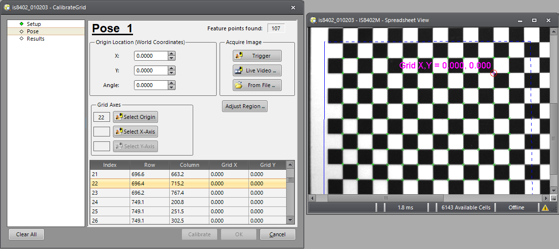
Configuring a Calibration Pattern Without a Fiducial Using the Grid Axes (optional)
If the calibration pattern being used does not have a fiducial, the origin and the X and Y coordinate axes must be defined by using the Grid Axes settings, which are present and enabled only when a calibration pattern without a fiducial is chosen.
-
After the image has been processed and the features have been extracted, click the Select Origin button.
-
This launches interactive graphics mode; from here, double-click on any of the highlighted points to select that point as the origin.
Note: Not all extracted features are capable of being an origin point; if a feature point is missing two adjacent points that are 90 degrees apart, it cannot be selected as an origin.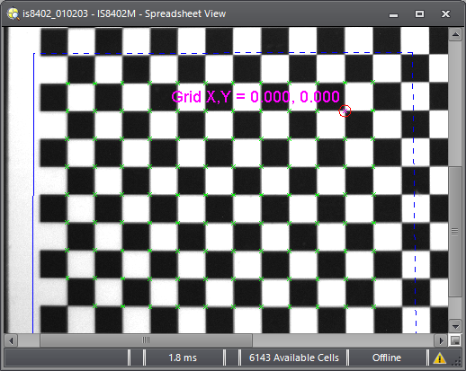
-
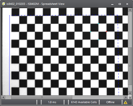
Once the origin is set, it will be highlighted and displayed in the Spreadsheet View, and the selected origin coordinate will be automatically highlighted in the data table, as shown below.
-
Next, click the Select X-Axis button; again, this launches interactive graphics mode, and from here, double-click on any of the highlighted points to select it as the X-axis.
-
Once the X-axis is set, it will be highlighted and displayed in the Spreadsheet View, and the selected X-axis coordinate will be automatically highlighted in the data table, as shown below.

-
Next, click the Select Y-Axis button; again, this launches interactive graphics mode, and from here, double-click on any of the highlighted points to select it as the Y-axis.
-
Once the Y-axis is set, it will be highlighted and displayed in the Spreadsheet View, and the selected Y-axis coordinate will be automatically highlighted in the data table.
- Finally, once the Origin, X-Axis and Y-Axis have been set, click the Calibrate button to proceed to the Results pane and finish the calibration, or select a Pose from the navigational pane if there are more poses to configure.
Configuring More Than One Pose Using the Pose Dialog (optional)
Automatic Mode:
When a single calibration pattern cannot fill the field of view, multiple calibration patterns must be used. In this illustration of a multiple pose scenario, the grid-of-dots pattern, with the fiducial marker, has been used.
- Specify the Origin Location (World Coordinates) for Pose 1.
-
Note: When Automatic mode is selected, the real-world coordinates of the origin in Pose 1 are the only world coordinate values that need to be entered. All additional poses, as long as the fiducial is found, are calibrated without specifying the origin for each pose.
- For each subsequent pose after Pose 1, a new image must be either loaded or acquired for each additional pose.
- Once all of the poses have been configured, click the Calibrate button to proceed to the Results dialog and finish the calibration.
User-Specified Mode:
If the calibration requires more than one pose with the pattern positioned in a different physical location for each pose, it will be necessary to accurately move the calibration pattern to several locations during the calibration sequence. This may be performed using a motion device, but the motion device control software is not automated in software, therefore, when a motion device is used, the motion device must be manually commanded by the motion device controller to move to each new pose before proceeding.
- Specify the Origin Location (World Coordinates) for each motion pose. The motion device pose must be manually entered for each view.
-
Note: The Origin Location (World Coordinates) in User-Specified mode is actually used to specify the motion pose of the motion device instead of the position and angle of the calibration plate's origin. Users do not need to determine the calibration plate's origin position, since the placement offset (in position and orientation) between the calibration plate and the motion device is unknown.
- For each subsequent pose after Pose 1, a new image must be acquired for each additional pose.
- Once all of the poses have been configured, click the Calibrate button to proceed to the Results dialog and finish the calibration.
Verifying the Calibration Using the Results Dialog
Once the Calibrate button has been pressed, the function will begin to calculate the best 2D transformation, and the dialog will automatically display the Results pane. The Results pane displays a calibration summary, which shows the total number of feature points found, and the average and maximum calibration error in pixels. The error level is assigned a rating based on the average error, using the following rating values:
- Excellent = Error <= 0.25
- Good = 0.25 < Error <= 0.5
- Marginal = 0.5 < Error <= 2.0
- Poor = 2.0 < Error <= 5.0
- Very Poor = 5.0 < Error
The rating can be viewed as the "score" of the total calibration. For instance, if the features are not evenly spaced on the grid, this will result in a lower score; or in a multiple pose calibration with User-Specified selected for the pose locations, if one of the poses is not accurately placed, this will also result in a lower score.
If the results are acceptable, click the OK button to finish the calibration.
CalibrateGrid Outputs
|
Returns |
A Calib data structure containing the coefficients that define the transformation between the two coordinate systems. |