Connect to the Vision System and Perform Hand-Eye Calibration
You perform a hand-eye calibration using the Cognex In-Sight 2D Robot Guidance plugin. This establishes the work plane within the field of view of the vision system, which determines the area where the robot can manipulate a part. The plugin creates a calibration file (.CXD) that you will later import into your main job.
Begin the calibration by defining three set points that will determine the height and width of the work plane.
- On the PolyScope main menu, select Program > Robot > Installation > Cognex. The Cognex window opens.
-
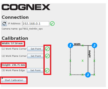
Under Connection, enter the IP Address of the vision system. The vision system name displays below that address.
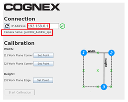
If the connection fails, refer to the following information to troubleshoot:
If this error displays: Do the following: Make sure the camera is online and the proper job file is loaded. In In-Sight Explorer, check that the camera is Online. The format of the IP address is invalid (example address: 192.168.0.1) In the robot software, check that the correct IP address for that camera is entered. Timeout reached. Make sure the network adapter is enabled in Setup Robot Network. In the robot software, check that the robot is on the correct network. -
Visually establish and make note of the size of the work plane that will include the part to be picked up by the robot. The graphic below illustrates sample points of width and height.
Note: In steps 4 through 6 below, before you click OK, you can verify that the vision system can still see the TCP by triggering an image manually in In-Sight EasyBuilder.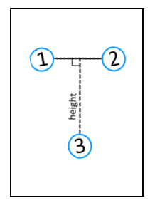
-
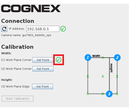
First, you will define the width of the work plane. Select the Set Point button for (1) Work Plane Corner. The Move tab displays. Use the controls to move the robot to the first corner point of the work plane, then select OK. A green check mark displays next to the first Set Point button on the Cognex window.
-
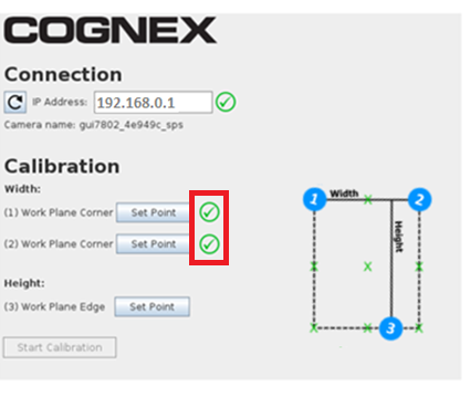
Select the Set Point button for (2) Work Plane Corner. The Move tab displays again. Use the controls to move the robot to the second corner of the work plane, then select OK. A green check mark displays next to the second Set Point button on the Cognex window.
-
Next, you will define the height using the third set point. Select the Set Point button for (3) Work Plane Edge. The Move tab displays again. Use the controls to move the robot to be in line with the far edge of the work plane, then select OK. A green check mark displays next to the third Set Point button on the Cognex window. The Width and Height display.
The Start Calibration button is now enabled.
- Before you start the calibration, review the width and height again to make sure they are satisfactory.
- To begin calibration, select Start Calibration. When the calibration completes, the following message displays: Calibration has finished.
- Select Start Program or Continue to close the window.
During calibration, the following occurs:
- The robot program directs the robot to 15 points within the field of view, and sends the coordinates to the vision system.
- The vision system acquires an image and determines the TCP location.
- The robot program maps the TCP coordinates to the vision system pixel coordinates.
When the calibration finishes, the Cognex In-Sight 2D Robot Guidance plugin does the following:
- Sends a message to the Robot tool of the calibration job that you previously created.
- Creates a calibration file with the file name you entered in the calibration job, along with a .CXD extension. You will import this calibration into your main job, which is where you will also train the part to be picked by the robot.