Getting Started
The In-Sight vision system is typically integrated into a factory automation environment, where it is programmed to perform a visual inspection of an object. Programming a vision system involves the following:
- Teaching the vision system what to look for, based on distinctive"features of interest" (also known as features) in the image.
- When to take a picture, and how best to illuminate the part.
- How to communicate the results of its analysis, and the actions to take, based on the results.
In-Sight Vision System Machine Vision Solution
A typical In-Sight solution to a machine vision problem involves the following:
- An In-Sight vision system, which contains a digital greyscale or color camera to acquire images and an imager to digitize them; a PC processor to run the programmed image analysis; and Input/Output hardware and communication links to report results and send/receive messages from other devices, such as an HMI, PLC or robot.
- In-Sight Explorer software, which is used to program In-Sight vision systems to perform image analysis and communicate with other devices.
- A lens that optimizes the feature(s) of interest in the Field of View (FOV).
- Some form of lighting to enhance the contrast of the features in the image.
Optional components include:
- An object-sensing synchronizing sensor (usually an optical or magnetic sensor) that triggers the vision system to acquire and process an image.
- An actuator to reject or sort parts based on the results o f the image analysis.
In this system, the synchronizing sensor indicates when a part or object is in position to be inspected. The synchronizing sensor triggers the In-Sight vision system to take a picture of the part or object as it passes by the vision system. During this phase, a pulse is also typically directed to the lighting mechanism, triggering the lights. The lighting used to illuminate the part or object is designed to highlight the features of interest and obscure or minimize the appearance of features that are not, such as shadows or reflections.
In the process of acquiring the image, the lens of the In-Sight vision system captures the light energy from the FOV (the physical area seen by the In-Sight vision system) and converts it into a digital format – a 2D grid of values called pixels, where each individual pixel corresponds to a location (X,Y coordinate) and a greyscale value (0-255; 0 = pure black and 255 = pure white) that expresses the light intensity at that location.
Example - Image Coordinates:
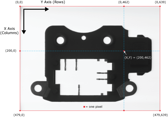
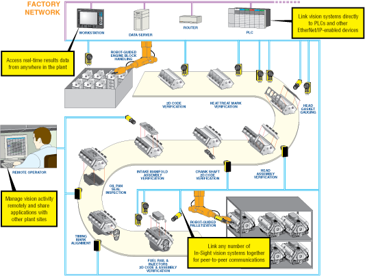
Then, the In-Sight vision system processes the image and performs its image analysis – counting, measuring and/or identifying objects, dimensions or other features in the image. Based on the results of the image analysis, the vision system passes or fails the part, sending a signal to the actuators and/or communicating the image analysis results to a networked device.
Example of networked In-Sight vision systems in a factory automation environment: