SLMP Scanner Factory Interface - In-Sight 5.x.x and Later Firmware
This topic covers the SLMP Scanner communication protocol for In-Sight vision systems running In-Sight 5.1.0 and later firmware.
- In this topic, PLC/MC and Robot Controllers are referred as "Automation Controller".
- The In-Sight 2000 series vision sensor does not support robot controllers.
SLMP Scanner Operations
SLMP Scanner is a command/response-based protocol, which originates from the In-Sight vision system, and the vision system must send read requests to the Automation Controller at periodic intervals to determine if there are changes in the control bits. This process is called "polling," and defines the polling cycle.
Polling Cycle
At the beginning of every polling cycle, the Vision Control Bit block will be read from the Automation Controller.The vision system will then process any bit state-change in the control block, in order.Some state-changes will require additional communication with the Automation Controller, such as reading a Job ID or the User Data fields, or writing the status block.These requests are placed in a queue.The polling mechanism processes these requests, in order, until there are either no more items in the queue, or the polling interval has been exceeded.Once the polling cycle has been completed, the cycle will not repeat.
- Any communication items that were placed in the queue from the previous cycle, but were not processed, will be the first items processed during the next cycle.If there are several items in the queue at the beginning of the cycle, at least one item from the queue will always be processed during each polling cycle, even if the processing might delay the next polling cycle.
- The Poll Interval (ms) parameter in the SLMP Scanner Settings dialog allows you to define the polling cycle interval.
Block Communications
The table below defines the actions that the In-Sight vision system will take in response to a status bit change in the Vision Control Bit block:
| Block | When Read/Written | Action |
|---|---|---|
| Vision Control Bit Block | Read at a user-specified periodic interval. |
Acquisition Trigger Soft Event Read or Write of any other block |
| Vision Status Bit Block | Written when the connection is first established, and when a new status is available. | |
| Input Word Block | Written when new inspection results are available, or when a job change occurs. | |
| Output Word Block | Read when the Set User Data bit changes from 0 to 1, or when the Execute Command bit changes from 0 to 1. | Setting the User Data Ack bit after reading the User Data field. |
| String Command Word Block | Read when the Initiate String Command bit changes from 0 to 1. | Processing the String Command. |
| String Command Result Block | Written when new string command results are available. | Setting the String Command Ack bit, after writing the String Command Result Word Block. |
Typical Sequence Diagram
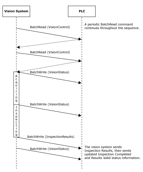
The following diagram illustrates the typical behavior of the In-Sight vision system in response to a Automation Controller triggering an acquisition and inspection cycle:
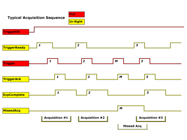
Typical Acquisition Sequence
An In-Sight vision system can be triggered by directly manipulating the Trigger Enable and Trigger bits in the Vision Control Block while monitoring the Trigger Ready, Trigger Ack, and Missed Acq bits in the Vision Status Block.
On initial start-up, the Trigger Enable bit will be False, and must be set to True to enable triggering. When the vision system is ready to accept triggers, the Trigger Ready bit will be set to True.
While the Trigger Enable and Trigger Ready bits are True, each time the vision system sees the Trigger bit change from 0 to 1, an image acquisition will be initiated. The Trigger bit should be held in the new state until that same state value has been seen in the Trigger Ack bit (which is a necessary handshake to guarantee that the change has been seen by the vision system).
During an acquisition, the Trigger Ready bit in the Vision Status Block will be cleared. The Exposure Complete bit will be set at the end of the acquisition, and can only be cleared by the Clear Exposure Complete bit.
To force a reset of the trigger mechanism, set the Trigger Enable bit to False until the Vision Status Block is 0. Then the Trigger Enable bit can be set to True and acquisitions re-enabled.
Typical Inspection Sequence
The Vision Status Block and Vision Control Block allow the Automation Controller to monitor the vision processing portion of the In-Sight vision system to determine when new results are available, and to request that the vision system queue any new results.
Inspection/Result Sequence
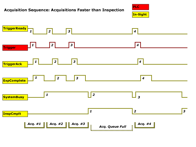
When an image is acquired by an In-Sight vision system, the image is placed in a queue for processing. While the vision system is processing the image, the System Busy bit is set. When the vision system has finished processing the image, the System Busy bit is cleared and the Inspection Completed bit is toggled.
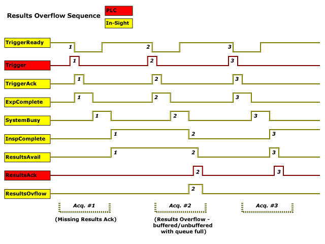
The Buffer Results Enable bit determines how inspection results are handled by the vision system. If the Buffer Results Enable bit is set to False, then the inspection results are immediately placed into the Output Word Block and the Results Valid bit is set to True. If the Buffer Results Enable bit is set to True, the new results are queued. The earlier inspection results remain in the Output Word Block until they are acknowledged by the Automation Controller, which sets the Inspection Results Ack bit to True.After the Results Valid bit is cleared, the Automation Controller should set the Inspection Results Ack bit back to False to allow the queued results to be placed into the Output Word Block (this is a necessary handshake to ensure that the results are received by the Automation Controller).
Vision Status Block Behavior
| Bit | Bit Name | Results If Buffering Is Disabled | Results If Buffering Is Enabled |
|---|---|---|---|
| 0 | System Busy |
Set when the vision system is running a job, loading a job or responding to user input. |
Set when the vision system is running a job, loading a job or responding to user input. |
| 1 | Inspection Complete |
Toggled on completion of an inspection. |
Toggled on completion of an inspection. |
| 2 | Results Buffer Overflow | Remains set to 0. | Set when the inspection results could not be queued because the Automation Controller failed to acknowledge the previous results, causing the results buffer to overflow. Cleared when an inspection result is successfully queued. |
| 3 | Results Valid |
Set when new results are placed in the Output Word Block.Stays set until the results are acknowledged by setting the Inspection Results Ack bit to True. |
Set when new results are placed in the Output Word Block. Stays set until the results are acknowledged by setting the Inspection Results Ack bit to True. |
Results Buffering
A queue for inspection results may be enabled. If enabled, this allows a finite number of inspection data results to be queued until the Automation Controller has time to read them. This is a useful feature for smoothing out data flows if different parts of the system (including the external Automation Controller) slow down for short periods of time.
In general, if inspections are occurring faster than the results can be sent out, the primary difference between buffering and not buffering is determining which results get discarded. If buffering is not enabled, the most recent results are kept, and the earlier result that the Automation Controller was unable to read is lost. Essentially, the most recent result will simply overwrite the earlier result. If buffering is enabled (and the queue becomes full), the most recent results are discarded until room becomes available in the results queue.
Typical Job Management Sequence
The Current Job ID field module indicates the current job ID of the In-Sight vision system, or 65535 if the current job does not have an ID. In order to load a job, the Automation Controller must set the vision system Offline by using the Set Offline bit. Next, the Command field is set to the desired job's ID and the Execute Command bit is set. Once the Command Completed bit goes to High, the Execute Command bit is reset.
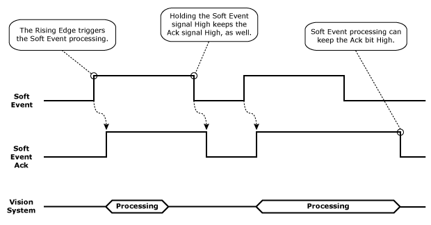
Typical Soft Event Sequence
A soft event can be used by the Automation Controller to trigger job specific behavior. Each soft event has a trigger and acknowledgment bit associated with it. The rising edge of the trigger bit causes the In-Sight vision system to process the action associated with the soft event. Upon initiation of the soft event, the vision system will set the Soft Event Ack bit to High. This bit will be held High until the Automation Controller resets the trigger bit, and the processing of the action associated with the soft event has been completed. If the soft event could not be triggered, the general fault bit will be set to High; this bit will remain High until an event is successfully triggered.
Typical String Command Sequence
In-Sight vision systems rely on Native Mode communications to support string commands for device interaction. Native Mode commands allow a string-style command to be issued from the Automation Controller to the vision system, which are especially useful when a command cannot be issued via the control bits.
SLMP Defined Data Blocks
The defined data blocks allow you to control where the vision system is reading and writing data to and from the Automation Controller. For easier application setup, the various control and status bits required for command functionality are grouped into contiguous blocks, which can be processed together. When setting up the interaction between the vision system and the Automation Controller, you will need to choose the starting address and device type for each block of data.
| Block | Byte | Bit 7 | Bit 6 | Bit 5 | Bit 4 | Bit 3 | Bit 2 | Bit 1 | Bit 0 |
|---|---|---|---|---|---|---|---|---|---|
|
Vision Control |
0 |
Set Offline |
Reserved |
Execute Command |
Inspection Results Ack |
Buffer Results Enable |
Trigger |
Trigger Enable |
|
| 1 | Reserved | ||||||||
| 2 | Reserved |
Clear Exposure Complete |
Clear Error |
Initiate String Command |
Set User Data |
||||
| 3 |
Soft Event 7 |
Soft Event 6 |
Soft Event 5 |
Soft Event 4 |
Soft Event 3 |
Soft Event 2 |
Soft Event 1 |
Soft Event 0 |
|
|
Vision Status |
0 | Online | Offline Reason |
Missed Acq |
Reserved |
Trigger Ack |
Trigger Ready |
||
| 1 | Error |
Command Failed |
Command Completed |
Command Executing |
Results Valid |
Results Buffer Overrun |
Inspection Completed |
System Busy |
|
| 2 | Reserved |
Job Pass |
Exposure Complete |
String Command Error |
String Command Ack |
Set User Data Ack |
|||
| 3 |
Soft Event Ack 7 |
Soft Event Ack 6 |
Soft Event Ack 5 |
Soft Event Ack 4 |
Soft Event Ack 3 |
Soft Event Ack 2 |
Soft Event Ack 1 |
Soft Event Ack 0 |
|
|
Output Word |
0..1 | Current Job ID | |||||||
| 2..3 |
Error Code |
||||||||
| 4..5 | Acquisition ID | ||||||||
| 6..7 | Inspection ID | ||||||||
| 8..9 | Inspection Result Code | ||||||||
| 10.. | Inspection Results | ||||||||
|
Input Word |
0..1 | Command | |||||||
| 2..3 | Reserved | ||||||||
| 4.. | User Data | ||||||||
|
String Command Word |
0..1 | String Command Length | |||||||
| 2.. | String Command | ||||||||
|
String Command Result Word |
0..1 | String Command Result Code | |||||||
| 2..3 |
String Command Result Length |
||||||||
| 4.. | String Command Result | ||||||||
Vision Control Block
Byte 0
| Bit | Name | Description |
|---|---|---|
| 7 | Set Offline |
When this bit is set, the In-Sight vision system is taken Offline until the bit is cleared again. |
| 6-5 | Reserved | Unused. |
| 4 | Execute Command | When set, the vision system loads the job ID specified in the Command field. The signal must be held high until the Command Completed signal is toggled. The falling edge of this signal (if prior to Command Complete) is interpreted as an abort request. |
| 3 | Inspection Results Ack | When the Buffer Results Enable bit is set, the Inspection Results Ack bit is set by the Automation Controller to acknowledge that it has received the InspectionCount, Inspection Result Code and Inspection Results data. The next set of inspection results is then sent to the Automation Controller. Clearing the Inspection Results Ack bit causes the vision system to set the ResultsValid bit if the buffer is not empty. |
| 2 | Buffer Results Enable | When this bit is set, the Inspection Count, Inspection Result Code and InspectionResults fields are held constant until they are acknowledged by setting the InspectionResults Ack bit. Up to eight inspections are held in the In-Sight vision system's buffer. The vision system will respond to the acknowledgment by clearing the ResultsValid bit. Once the InspectionResults Ack bit is cleared and there is a new set of results sent to the Automation Controller, the ResultsValid bit will no longer be cleared. If the Inspection Results Ack bit is cleared and there are no more results in the vision system's buffer that are to be sent to the Automation Controller, the ResultsValid bit remains cleared. |
| 1 | Trigger |
Setting this bit triggers an acquisition when the following conditions are met:
Note:
|
| 0 | Trigger Enable | This field is set to enable triggering via the Trigger bit. Clear this bit to disable the network triggering mechanism. |
Byte 1
| Bit | Name | Description |
|---|---|---|
| 7-1 | Reserved | Unused. |
Byte 2
| Bit | Name | Description |
|---|---|---|
| 7-4 | Reserved | Unused. |
| 3 | Clear Exposure Complete |
While this signal is High, the Exposure Complete status will remain reset. Once this signal is set to Low, the Exposure Complete status will be set to High on the next exposure completion. |
| 2 | Clear Error |
When this bit is set, it will clear the Error and Error Code signals; the Clear Error bit should be held high until the Error bit has been cleared. If an error has been queued, clearing this bit will cause the Error and Error Code signals to be set to the next queued error code. |
| 1 | Initiate String Command | When this bit is set, it will read the data from the String Command field and execute the string command. Upon reading the command, the String Cmd Ack bit will be set. This bit should be held High until the vision system sets the String Cmd Ack bit to ensure that the vision system has received the command. |
| 0 | Set User Data | This command is used by the Automation Controller to indicate to the In-Sight vision system that it should transfer the User Data field into a holding buffer for consumption by the vision system. |
Byte 3
| Bit | Name | Description |
|---|---|---|
| 7 | Soft Event 7 | Allows Spreadsheet soft events to be triggered. Setting any of these bits causes the associated soft event in the Spreadsheet to be triggered. |
| 6 | Soft Event 6 | |
| 5 | Soft Event 5 | |
| 4 | Soft Event 4 | |
| 3 | Soft Event 3 | |
| 2 | Soft Event 2 | |
| 1 | Soft Event 1 | |
| 0 | Soft Event 0 |
Vision Status Block
Byte 0
| Bit | Name | Description | |||||||||||||||
|---|---|---|---|---|---|---|---|---|---|---|---|---|---|---|---|---|---|
| 7 | Online | This bit is set when the In-Sight vision system is Online, and cleared when the vision system is Offline. When the vision system is Offline, examine the Offline Reason field to determine the reason. | |||||||||||||||
| 6-4 | Offline Reason |
This field is a 3-bit field used to identify the cause of why an In-Sight
vision system is Offline:
Note: It is possible to have multiple devices holding the In-Sight vision system Offline. In this scenario, this field will return the channel with the lowest reason code. |
|||||||||||||||
| 3 | Missed Acq |
Set when an In-Sight vision system misses an acquisition trigger, regardless how the acquisition was triggered; cleared when
an acquisition is successfully triggered.
Note: If the Trigger bit is set, but the vision system is offline, the Missed Acq and Trigger Ack bits will both be set. |
|||||||||||||||
| 2 | Reserved | Unused. | |||||||||||||||
| 1 | Trigger Ack |
Indicates when an In-Sight vision system has been triggered by the Trigger
bit being set; this bit will stay set until the Trigger
bit is cleared.
In addition, the Acquisition ID can be latched to the rising edge of this bit. Note: If the Trigger bit is set, but the vision system is offline, the Missed Acq and Trigger Ack bits will both be set. |
|||||||||||||||
| 0 | Trigger Ready |
Indicates when an In-Sight vision system can accept a new trigger via the Trigger bit. This field is true when the vision system is Online, the Trigger Enable bit is set, the AcquireImage function's Trigger parameter is set to Network, External or Industrial Ethernet, and the vision system is not currently acquiring an image. Note: The Industrial Ethernet Trigger type should be used when the trigger is coming from an Automation Controller.
|
Byte 1
| Bit | Name | Description |
|---|---|---|
| 7 | Error | This bit is set when an error has occurred, which is defined in the Error Code field. |
| 6 | Command Failed | This bit is set to 1 to indicate that Job Load has failed to run to completion. It is cleared when a new job is loaded by the PLC/HMI. If the job is changed through In-Sight Explorer, this bit does not change. This bit is always set prior to setting the Command Completed bit. |
| 5 | Command Completed | When a Command completes the Command Executing bit goes low and if the Execute Command bit is still high, the Command Completed bit is set. If the Command did not successfully complete, the Command Failed bit is also set. Note: The camera clears the Command Completed bit when the Execute Command bit goes low. |
| 4 | Command Executing | This bit is set to 1 when Job Load is started. The Command Completed and Command Failed bits will be set prior to the falling edge of this bit. |
| 3 | Results Valid |
Set when the Inspection Count, Inspection Result Code, Inspection Results and/or Job Pass bits are set. The bit is cleared when the Inspection Results Ack bit is set. Note: If job processing is enabled to occur in overlapped mode, either the Buffer Results Enable bit should be enabled/set, or the Inspection Completed bit should be used to latch the inspection results.
|
| 2 | Results Buffer Overrun |
This field is set when the Buffer Results Enable bit is set and the In-Sight vision system has discarded a set of inspection results because the Automation Controller has not acknowledged the results by setting the InspectionResults Ack bit.Up to eight inspections are held in the vision system's buffer; therefore, this bit is set when the ninth inspection is added to the buffer. The ninth inspection, and all subsequent inspections, will be dropped until there is room in the buffer (when the results have been acknowledged out). The bit is not cleared until a valid inspection occurs and a previous inspection is not overwritten. |
| 1 | Inspection Completed | This bit is toggled upon the completion of an inspection. It is guaranteed to be toggled after the Inspection Count, Inspection Result Code, Inspection Results and/or Job Pass bits are sent to the PLC. |
| 0 | System Busy |
Set when the vision system is running a job, loading a job or responding to user input. |
Byte 2
| Bit | Name | Description | ||||
|---|---|---|---|---|---|---|
| 7-5 | Reserved | Unused. | ||||
| 4 | Job Pass |
This bit is set if the most recent job passed as configured in the Job Pass/Fail Cell Setup dialog. This bit is cleared if the job did not pass.
The behavior of the Job Pass bit will depend on whether or not results buffering is disabled or enabled:
|
||||
| 3 | Exposure Complete | This bit is set upon the completion of the In-Sight vision system's exposure period, and is reset by the Clear Exposure Complete bit. This bit will be held in a reset state if the Clear Exposure Complete signal is set to High. | ||||
| 2 | String Command Error | This bit indicates whether or not the result of the previous string command returned a failure code. | ||||
| 1 | String Command Ack | This bit is set when the vision system completes processing of a command and generates a response to the command. After the vision system has set this bit, the Automation Controller can safely read the string command response data. The bit will be reset after the Automation Controller clears the Initiate String Command bit. The Automation Controller should clear the Initiate String Command bit and wait for the String Command Ack bit to return to a Low state before initiating a new command. | ||||
| 0 | Set User Data Ack | This bit is set to acknowledge completion of the Set User Data command. |
Byte 3
| Bit | Name | Description |
|---|---|---|
| 7 | Soft Event Ack 7 | These bits are used to indicate that the Soft Event command was received. |
| 6 | Soft Event Ack 6 | |
| 5 | Soft Event Ack 5 | |
| 4 | Soft Event Ack 4 | |
| 3 | Soft Event Ack 3 | |
| 2 | Soft Event Ack 2 | |
| 1 | Soft Event Ack 1 | |
| 0 | Soft Event Ack 0 |
Output Word Block
Byte 0 - 1
| Name | Description |
|---|---|
| Current Job ID | A 16-bit integer that denotes the ID number of the currently running job on the vision system, or 65535 if the current job does not have an ID number. This field is updated when the job is changed on the vision system, regardless of method of job change. |
Byte 2 - 3
| Name | Description | |||||||||||||||||||||||||||
|---|---|---|---|---|---|---|---|---|---|---|---|---|---|---|---|---|---|---|---|---|---|---|---|---|---|---|---|---|
| Error Code |
A 16-bit numeric representation of the error that has occurred:
|
Byte 4 - 5
| Name | Description |
|---|---|
| Acquisition ID | This ID increments at the beginning of an acquisition and when the Trigger Ack bit is set; can be used to synchronize an acquisition with its Inspection Results. |
Byte 6 - 7
| Name | Description |
|---|---|
| Inspection ID | The acquisition ID associated with this set of results. |
Byte 8 - 9
| Name | Description |
|---|---|
| Inspection Result Code | The inspection result code is defined by the Result Code parameter of the WriteResultsBuffer function. For more information, see WriteResultsBuffer. |
Byte 10 - 1914
| Name | Description |
|---|---|
| Inspection Results | Inspection result data written from the spreadsheet, using the WriteResultsBuffer function. |
Input Word Block
Byte 0 - 1
| Name | Description |
|---|---|
| Command |
This is a 16-bit integer used to either indicate the Job ID number (0-999) of the job to load. The job load is executed when the Execute Command bit is set by the PLC. The Command field must be held constant between the rising edge of the Execute Command signal and the rising edge of the Command Completed signal, or the results will be indeterminate. |
Byte 2 - 3
| Name | Description |
|---|---|
| Reserved | Unused. |
Byte 4 - 1919
| Name | Description |
|---|---|
| User Data | Data buffer which can be read into the spreadsheet using the ReadUserDataBuffer or ReadLatchedUserDataBuffer function. |
String Command Word Block
Byte 0 - 1
| Name | Description |
|---|---|
| String Command Length | The length of the Native Mode command. |
Byte 2 - 1919
| Name | Description |
|---|---|
| String Command | The Native Mode command to be processed by the vision system. |
String Command Result Word Block
Byte 0 - 1
| Name | Description |
|---|---|
| String Command Result Code |
The response code for the Native Mode command, which can be used to determine if the command was successful, or failed. Note: Each Native Mode command returns a 1 for a successful execution, while each command has specific error codes for cases of failure. Review the individual Native Mode command topics for more information about the failure codes.
|
Byte 2 - 3
| Name | Description |
|---|---|
| String Command Result Length | The length of the Native Mode command's Response Data, in bytes. |
Byte 4 -
| Name | Description |
|---|---|
| String Command Result | The Native Mode command's result string, an ASCII string representation of the data returned by the command. |
Available Device Types and Ranges on Mitsubishi Automation Controller
The following table describes the available devices and ranges on Mitsubishi Automation Controller when communicating with SLMP Scanner.
| Controller Type | Controller Bit Block, Status Bit Block | Input Word Block, Output Word Block, Command Word Block, Command Result Block | |||
|---|---|---|---|---|---|
| Device Type | Range | Device Type | Range | ||
| PLC/MC | iQ-R/Q/L Series | X, Y, B, W | 0~FFFF (Hex) | D, R, ZR, TN, CN | 0~65535 |
| M, L, F, D, R, ZR | 0~65535 | W | 0~FFFF (Hex) | ||
| iQ-F Series | X, Y | 0~177777 (Oct) | D | 0~65535 | |
| M, F, D | 0~65535 | ||||
| FX Series | X, Y | 0~177777 (Oct) | D, R, TN, CN | 0~65535 | |
| M, D, R, S | 0~65535 | ||||
| Robot Controller | CR800-D Series | D | 0~65535 | D | 0~65535 |
Errors on GX Works
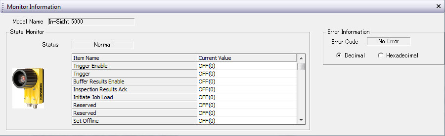
Error Codes on Monitor Information
The following table shows the Error Codes displayed within the Monitor Information section in the Sensor/Device Monitor for Ethernet Configuration dialog.
| Error Code | Description |
|---|---|
| 0 | SLMP is running / connected |
| 1 | SLMP connecting... |
| 3 | SLMP Fault (default error code if no other error details can be obtained) |
| 7 | Error in status block |
| 8 | Error in control block |
| 9 | Error in output block |
| 10 | Error in input block |
| 11 | Error in command block |
| 12 | Error in command result block |
| 13 | SLMP protocol not started |
| 14 | Protocol pending sensor reboot (after a protocol change) |