Configure Discrete Output Details
The Output Details dialog is used to configure individual output line parameters from within the Discrete I/O Settings dialog.
- From the Sensor menu, click Discrete I/O Settings.
-
From the Discrete I/O Settings dialog, choose an output line to configure and click Details.
Note: No output details are configurable for High, Low, System Busy, Online/Offline, Lifeline, IO Module Standby and Job Pass/Fail Cell Signal Types.The appearance of the Output Details dialog will vary, depending on the output line Signal Type:
Signal Type
Output Details Dialog
Programmed (Default)
Acquisition Start
Acquisition End
Job Load OK
Job Load Fail
ERR: Missed Acquisition
ERR: Tracking Overrun
ERR: Tracking Queue Full
Job Completed
Strobe
Output Details Dialog Controls
-
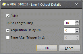
Pulse: When checked, the output will be pulsed for the duration of the Pulse Length. Uncheck this checkbox for steady-state output.
Note: The output must be pulsed when the Acquisition Delay (N) value is greater than 0. -
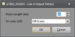
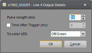
Pulse Length (ms): Duration of an output pulse.
Vision System/Vision Sensor Minimum Pulse Length Maximum Pulse Length Default Pulse Length General-Purpose Output High-Speed Output In-Sight Micro 1000 series (except 1402, 1412 and 1500) 10ms 10ms 1000ms 10ms In-Sight Micro 1402, 1412 and 1500 10ms 1ms 1000ms 10ms In-Sight 5000 series 10ms 10ms 1000ms 10ms In-Sight 70xx - 74xx series 10ms 1ms 1000ms 10ms In-Sight 7000 Gen2 series 1ms 1ms 1000ms 10ms In-Sight 8000 series 1ms 1ms 1000ms 10ms In-Sight 9902L 1ms 1ms 1000ms 10ms In-Sight 9912 1ms 1ms 1000ms 10ms Note:- When using the CIO-Micro or CIO-Micro-CC I/O module with supported vision systems, the minimum pulse length for general-purpose outputs is limited by the Update Time setting in the I/O Module Configuration dialog. For example, if the Update Time is 20ms, the minimum pulse length cannot be set below 30ms.
- For the In-Sight 7000 Gen2 series and 8000 series vision systems, the minimum pulse length of 1ms is only supported using In-Sight firmware version 5.5.0 and higher. If using an earlier version of firmware, the minimum pulse length is 10ms.
-
Acquisition Delay (N): The number of acquisition or tracking pulses (0 to 1000) to delay the output after a signal pulse is received by an output Line. If Acquisition Delay = 0, then the In-Sight vision system updates the output line immediately on evaluating the WriteDiscrete function. If Acquisition Delay is greater than 0, the output Line is always pulsed.
Note: Acquisition Delay and Time After Trigger cannot be used concurrently. -
Time After Trigger (ms): When this checkbox is selected, the output will be fired after the specified amount of time (0 to 10000 ms).
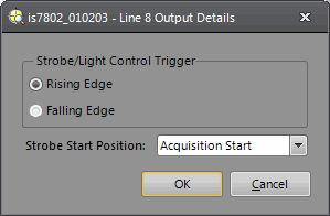
Note: Acquisition Delay and Time After Trigger cannot be used concurrently. - Strobe/Light Control Trigger: The rising or
falling edge of the signal can be used to trigger a strobe.
- NPN Configuration: If set to Rising Edge, the signal is HIGH when the image sensor is being exposed, otherwise the signal is LOW. If set to Falling Edge, the signal is LOW when the image sensor is being exposed, otherwise the signal is HIGH. Always pulsed for the duration of the exposure. The Exposure time must be 0.50 ms greater than the strobe pulse duration specified on the external strobe device.
PNP Configuration: If set to Rising Edge, the signal is LOW when the image sensor is being exposed, otherwise the signal is HIGH. If set to Falling Edge, the signal is HIGH when the image sensor is being exposed, otherwise the signal is LOW. Always pulsed for the duration of the exposure. Always pulsed for the duration of the exposure. The Exposure time must be 0.50 ms greater than the strobe pulse duration specified on the external strobe device.
Note:- For the In-Sight 5600 series, 5705, 5705C, 5715 and 9902L vision systems, the strobe behavior is inverted (i.e., for NPN wiring configurations, the Rising Edge and Falling Edge behave like a PNP configuration).
- If using a strobe with the In-Sight 9902L line scan vision system:
- The strobe should use a PNP wiring configuration and the Strobe/Light Control Trigger should be set to Rising Edge.
- When the vision system receives an acquisition trigger, the output line sends a pulse and the strobe flashes for the duration of the Exposure time. Once exposure is complete, there must be a minimum of 100µs before the next acquisition trigger is received or the strobe might not function correctly.
- Strobe Start Position: Specifies when the strobe should pulse. This option is not supported for the In-Sight 9902L vision system.
- Acquisition Start: Specifies that the strobe will pulse as the vision system begins its acquisition. Supported on all models except the In-Sight 8405 vision system.
- Camera Trigger: Specifies that the strobe will pulse upon receiving a camera trigger event. Supported on all models except the In-Sight 8405 vision system.
All Rows Exposed: Specifies that the strobe will pulse only when all pixel rows are exposed. Supported on the In-Sight 8405 vision system only.
Note: If using a strobe with the In-Sight 8405 vision system, a minimum Exposure value of 72ms is recommended for a full frame image capture, to ensure that all pixel rows are exposed when the strobe is pulsed. For more information, see In-Sight 8405 Rolling Shutter Operation.
-
Tri-Color LED: Configures the behavior of tri-color LED lines. (Off/Green, Off/Red, Red/Green; default = Off/Green) This option is only available if the line supports tri-color LEDs.
Note: This option is supported with In-Sight 7000 Gen2 series and In-Sight 9000 series vision systems for the Pass/Fail LED, but is not supported if Pass/Fail Job Cell is the selected Output Signal Type.