SLMP Scanner Settings Dialog
The SLMP Scanner Settings dialog configures an In-Sight vision system to communicate with a Mitsubishi Automation Controller (PLC, and Motion Controller or Robot Controller).
- In this topic, PLC/MC and Robot Controllers are referred as "Automation Controller".
- The In-Sight 2000 series vision sensor does not support robot controllers.
Display the SLMP Scanner Settings Dialog
Mitsubishi PLC Controllers (iQ-R/Q/L Series, iQ-F Series or FX Series)
-
From the Network Settings dialog, with the SLMP Scanner Industrial Ethernet Protocols option enabled, click the Settings button.
Mitsubishi Robot Controllers
-
From the Network Settings dialog, with the Robots option enabled, click the Settings button.
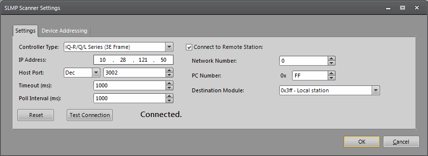
Settings Tab Controls
The Settings tab is used to configure the connection information required to establish a connection between the In-Sight vision system and the Mitsubishi Automation Controllers (PLC/MC and Robot Controller).
-
Controller Type: Specifies the type of Mitsubishi Automation Controller to communicate with.
Note: Available Controller Types vary, depending on the settings on the Network Settings dialog.-
PLC/MC: iQ-R/Q/L Series (3E Frame), iQ-F Series (3E Frame) or FX Series (1E Frame). Default = iQ-R/Q/L Series (3E Frame).
Note: The iQ-F Series (3E Frame) option is not available on the In-Sight vision systems running In-Sight 4.x.x firmware. - Robot: CR800-D Series (3E Frame)
-
-
IP Address: Specifies the IP address of the Automation Controller that will be connected to by the In-Sight vision system.
-
Host Port: Specifies the TCP port number, in decimal (Dec: 1 - 65535) or in hexadecimal (Hex: 1 - FFFF) format, of the SLMP channel that will be used by the Automation Controller (default = 12288 in Dec).
Note:- This value should match the Host Port setting established on the SLMP Port of the Mitsubishi Automation Controller.
- The format of the Host Port number will be reset to decimal (Dec) when In-Sight Explorer is closed.
-
Timeout (ms): Specifies the timeout (5 to 30000; default = 1000), in milliseconds, for a response from the Automation Controller to an SLMP message.
-
Poll Interval (ms): Specifies the amount of time (5 to 30000; default = 1000), in milliseconds, between successive polls of the Vision Control block on the Automation Controller.
- Connect to Remote Station: By default, the checkbox is unchecked and the In-Sight vision system is directly connected to the Automation Controller with an Ethernet Module specified by the entered IP Address.
- When this checkbox is checked and iQ-R/Q/L Series (3E Frame), iQ-F Series (3E Frame) or CR800-D Series (3E Frame) is the selected Controller Type, the Network Number, PC Number and Destination Module controls are enabled.
- When this checkbox is checked and FX Series (1E Frame) is the selected Controller Type, the PC Number control is enabled.
-
Network Number: Specifies the SLMP network number (0 to 239; default = 0) that will be used to communicate (0 = the local network).
-
PC Number (hex): Specifies the station identifier on the specified network of the destination module in hexadecimal.
Hex Description 0xFF (default) A direct connect to local station. 0x7E The Master station on CC-Link IE field. 0x1 - 0x78 A station on the CC-Link IE field network adapter -
Destination Module: Specifies the identifier of the device module that the vision system will be connected to.
Identifier Module Type 0x3FF (default) Local Station 0x3D0 Control System CPU 0x3D1 Standby System CPU 0x3D2 System A CPU 0x3D3 System B CPU 0x3E0 CPU 1 0x3E1 CPU 2 0x3E2 CPU 3 0x3E3 CPU 4 -
Reset button: Press the Reset button to restore the values to the default settings.
-
Test Connection button: The Test Connection button is used to establish a "test" connection between the In-Sight vision system and the Mitsubishi Automation Controller over SLMP. Pressing the Test Connection button will initiate a connection, and an attempt will be made to establish a connection. After 30 seconds, if the connection is not established or goes into an error state before the timeout, an error message will be displayed, indicating an error reported by SLMP.
Note: If you attempt to apply changes to the SLMP Scanner Settings dialog, but SLMP is not enabled on the vision system, a message will be displayed indicating that the vision system must be restarted to enable SLMP. The vision system must be restarted to enable SLMP.
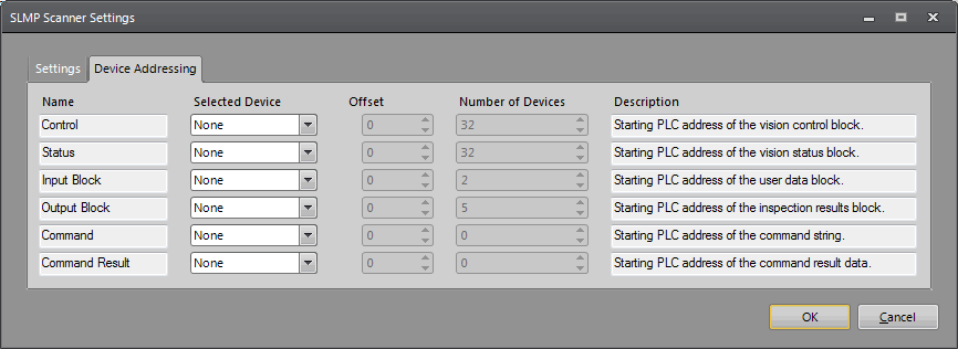
Device Addressing Tab
The Device Addressing tab is used to configure the Automation Controller device addresses and sizes of the various data blocks that will be communicated from the In-Sight vision system to the Mitsubishi Automation Controller. The Device Type and size of the data blocks vary, depending on the Controller Type (iQ-F/R/Q/L Series or FX Series) defined in the Settings Tab.
- Name column: Specifies the name (read-only) of the data block that will be communicated to or from the Automation Controller.
- Selected Device column: Specifies the Automation Controller device that will be used to read or write the data block. The available Automation Controller devices are as follows:
PLC/Motion Controllers:
Controller Type Device iQ-R/Q/L Series X - Input Relay; Y - Output Relay; M - Internal Relay; L - Latch Relay; F - Annunciator; B - Link Relay; D - Data Register; W - Link Register; R - File Block Register; and ZR - File Register. iQ-F Series X - Input Relay; Y - Output Relay; M - Internal Relay; F - Annunciator; D - Data Register. FX Series X - Input Relay; Y - Output Relay; M - Internal Relay; D - Data Register; R - Extension Register; and S - State Relay. Robot Controllers:
Controller Type Device CR800-D Robot Controller D - Data Register
- Offset column: Specifies an offset within the device table used to read or write the data block. The offset value should be entered in decimal, hexadecimal or octal, depending on the Selected Device type.
PLC/Motion Controllers:
Controller Type Device iQ-R/Q/L Series Decimal: M - Internal Relay; L - Latch Relay; F - Annunciator; D - Data Register; R - File Block Register; and ZR - File Register.
- Hexadecimal: X - Input Relay; Y - Output Relay; B - Link Relay; and W - Link Register.
iQ-F Series Decimal: M - Internal Relay; F - Annunciator; D - Data Register.
- Octal: X - Input Relay; Y - Output Relay.
FX Series - Decimal: M - Internal Relay; D - Data Register; R - Extension Register; and S - State Relay.
- Octal: X - Input Relay; and Y - Output Relay.
Robot Controllers:
Controller Type Device CR800-D Robot Controller - Decimal: D - Data Register
-
Number of Devices column: Specifies the size of the data block that will be communicated with the Automation Controller. The size is expressed in units of Automation Controller "devices" (either words or bits), and is configurable only for those data blocks that do not have a fixed size, or where the size is automatically set by the referenced FormatInputBuffer or FormatOutputBuffer functions. The maximum data size for the Input Block, Output Block, Command and Command Result varies depending on the selected Controller Type (iQ-R/Q/L Series, iQ-F Series or FX Series).
- PLC/Motion Controllers
-
iQ-R/Q/L Series
Name Selected Device Offset Number of Devices Description Control None (default); X - Input Relay; Y - Output Relay; M - Internal Relay; L - Latch Relay; F - Annunciator; B - Link Relay; D - Data Register; W - Link Register; R - File Block Register; ZR - File Register 0 - 32 (read-only) The starting PLC address of the vision control data block. Status None (default); X - Input Relay; Y - Output Relay; M - Internal Relay; L - Latch Relay; F - Annunciator; B - Link Relay; D - Data Register; W - Link Register; R - File Block Register; ZR - File Register 32 (read-only) The starting PLC address of the vision status data block. Input Block None (default); D - Data Register; W - Link Register; R - File Block Register; ZR - File Register 2 devices1 + Input Data length (in words)
(Maximum: 960 words)
The starting PLC address of the inspection results data block. Output Block None (default); D - Data Register; W - Link Register; R - File Block Register; ZR - File Register 5 devices2 + Output Data length (in words)
(Maximum: 960 words)
The starting PLC address of the user data block. Command None (default); D - Data Register; W - Link Register; R - File Block Register; ZR - File Register 0 - 960 (default = 0) The starting PLC address of the command string. Command Result None (default); D - Data Register; W - Link Register; R - File Block Register; ZR - File Register 0 - 960 (default = 0) The starting PLC address of the command result data. 1 2 devices (4 bytes/2 words) are used for the Job Load ID and User Length.
2 5 devices (10 bytes/5 words) are used for the Job ID, Acquisition ID, Inspection ID, Inspection Result Code and Inspection Result Length.
-
iQ-F Series
Name Selected Device Offset Number of Devices Description Control None (default); X - Input Relay; Y - Output Relay; M - Internal Relay; F - Annunciator; D - Data Register 0 - 32 (read-only) The starting PLC address of the vision control data block. Status None (default); X - Input Relay; Y - Output Relay; M - Internal Relay; F - Annunciator; D - Data Register 32 (read-only) The starting PLC address of the vision status data block. Input Block None (default); D - Data Register 2 devices1 + Input Data length (in words)
(Maximum: 960 words)
The starting PLC address of the inspection results data block. Output Block None (default); D - Data Register 5 devices2 + Output Data length (in words)
(Maximum: 960 words)
The starting PLC address of the user data block. Command None (default); D - Data Register 0 - 960 (default = 0) The starting PLC address of the command string. Command Result None (default); D - Data Register 0 - 960 (default = 0) The starting PLC address of the command result data. 1 2 devices (4 bytes/2 words) are used for the Job Load ID and User Length.
2 5 devices (10 bytes/5 words) are used for the Job ID, Acquisition ID, Inspection ID, Inspection Result Code and Inspection Result Length.
-
FX Series
Name Selected Device Offset Number of Devices Description Control None (default); X - Input Relay; Y - Output Relay; M - Internal Relay; D - Data Register; R - Extension Register; S - State Relay 0 - 32 (read-only) The starting PLC address of the vision control data block. Status None (default); X - Input Relay; Y - Output Relay; M - Internal Relay; D - Data Register; R - Extension Register; S - State Relay 32 (read-only) The starting PLC address of the vision status data block. Input Block None (default); D - Data Register; R - Extension Register 2 devices1 + Input Data length (in words)
(Maximum: 64 words)
The starting PLC address of the inspection results data block. Output Block None (default); D - Data Register; R - Extension Register 5 devices2 + Output Data length (in words)
(Maximum: 64 words)
The starting PLC address of the user data block. Command None (default); D - Data Register; R - Extension Register 0 - 64 (default = 0) The starting PLC address of the command string. Command Result None (default); D - Data Register; R - Extension Register 0 - 64 (default = 0) The starting PLC address of the command result data. 1 2 devices (4 bytes/2 words) are used for the Job Load ID and User Length. 2 5 devices (10 bytes/5 words) are used for the Job ID, Acquisition ID, Inspection ID, Inspection Result Code and Inspection Result Length.
-
- Robot Controllers
-
CR800-D Series
Name Selected Device Offset Number of Devices Description Control None (default); D - Data Register 0 - 32 (read-only) The starting Robot Controller address of the vision control data block. Status None (default); D - Data Register 32 (read-only) The starting Robot Controller address of the vision status data block. Input Block None (default); D - Data Register 2 devices1 + Input Data length (in words)
(Maximum: 960 words)
The starting Robot Controller address of the inspection results data block. Output Block None (default); D - Data Register 5 devices2 + Output Data length (in words)
(Maximum: 960 words)
The starting Robot Controller address of the user data block. Command None (default); D - Data Register 0 - 960 (default = 0) The starting Robot Controller address of the command string. Command Result None (default); D - Data Register 0 - 960 (default = 0) The starting Robot Controller address of the command result data. 1 2 devices (4 bytes/2 words) are used for the Job Load ID and User Length.
2 5 devices (10 bytes/5 words) are used for the Job ID, Acquisition ID, Inspection ID, Inspection Result Code and Inspection Result Length.
-
- PLC/Motion Controllers
- When Selected Device is set to None, restart the In-Sight vision system once the SLMP Scanner settings are configured or changed.
- If a data block's Selected Device parameter is set to None, the data block will not be communicated to or from the Automation Controller.
- The TN and CN device types are not supported because the input and output data blocks are communicated inline with the control and status word data.
- The iQ-R/Q/L series, iQ-F series and CR800-D Series can handle most message frame formats currently available (3E frame). However, the FX Series can only handle the first generation of the protocol message frame (1E frame), and the amount of data that can be transmitted in a packet is limited.
Maximum Data Size
| iQ-R/Q/L Series, iQ-F Series and CD800-D Series | FX Series | |
|---|---|---|
| Batch Read Bits | 7904 bits | 256 bits |
| Batch Read Words | 960 words | 64 words |
| Batch Write Bits | 7904 bits | 160 bits |
| Batch Write Words | 690 words | 64 words |