Interactive Graphics Mode
The parameters for many In-Sight functions, particularly Vision Tool functions, can be configured by adjusting a graphic on top of the image. For more information, see Vision Tools Functions.
- An interactive graphic can be used to easily set the size, position, and rotation for a region of interest, or for training a model region.
- You can adjust an interactive graphic from any spreadsheet cell that contains a function with a corresponding graphic, as well as from any parameter's value with a corresponding graphic on a property sheet. For more information, see Property Sheet.
- Interactive graphics mode can be accessed in either standard view or Custom View of the spreadsheet, as permitted by the user's access level. For more information, see Custom View Settings Dialog and User Access Settings Dialog.
Use Interactive Graphics Mode
- Select a spreadsheet cell or property sheet value
with an associated interactive graphic (the Edit
Cell Graphic
 icons will appear grayed out when
their corresponding functions are not available in the current context).
icons will appear grayed out when
their corresponding functions are not available in the current context).
-
There are four methods for entering Interactive Graphics Mode:
- Press F9.
- Click the Edit Cell Graphic button
on the Job Edit toolbar.
- From the property
sheet, click the Edit Cell Graphic button on the property sheet's toolbar.
- Right-click and select Cells Graphics... from the shortcut menu. For more information, see Right-Click Menu.
- The semitransparent spreadsheet overlay or property
sheet will disappear, and the interactive graphic will be displayed on
top of the image. There are six types of interactive graphics modes: annulus,
regions, circles, crosses, points, and lines.
The type of Interactive Graphics Mode icon displayed in the interactive
graphic depends on the type of input required by the cell or value:
Annulus:
Move
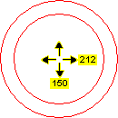
Repositions the annulus on the image. The pixel coordinates of the center point of the annulus are displayed. When using the mouse, the pixel coordinates are displayed in the status bar.
Action Keyboard Mouse Move left
LEFT ARROW
Click inside the annulus and drag leftward.
Move right
RIGHT ARROW
Click inside the annulus and drag rightward.
Move up
UP ARROW
Click inside the annulus and drag upward.
Move down
DOWN ARROW
Click inside the annulus and drag downward.
Cycle to Resize mode
F9
N/A
Change annulus color
SHIFT+F9
N/A
Undo an action
CTRL+Z
On the Standard toolbar, click the Undo  button.
Redo an action
CTRL+Y
On the Standard toolbar, click the Redo  button.
Resize
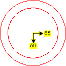
Increases or decreases the inner or outer radius of the annulus from the center. The inner radius (arrow right) and outer radius (arrow down) are indicated, in pixels. When using the mouse, the inner radius and outer radius values are displayed in the status bar.
Action Keyboard Mouse Decrease inner radius
UP ARROW
Click the edge of the inner circle and drag toward the center.
Increase inner radius
DOWN ARROW
Click the edge of the inner circle and drag away from the center.
Decrease outer radius
LEFT ARROW
Click the edge of the outer circle and drag toward the center.
Increase outer radius
RIGHT ARROW
Click the edge of the outer circle and drag away from the center.
Cycle to Move mode
F9
N/A
Change annulus color
SHIFT+F9
N/A
Undo an action
CTRL+Z
On the Standard toolbar, click the Undo
button.Redo an action
CTRL+Y
On the Standard toolbar, click the Redo
button.- Regions: Regions behave in three different ways,
depending on the value of the Bend parameter:
- Bend = 0: The region behaves as a Rectangle.
- 0 < Bend < 120: The region behaves as an Arc Segment.
Bend >= 120: The region behaves as a Circle.
These different behaviors are evident when working in Resize mode only:
Move
Repositions the region on the image. The pixel coordinates of the center of the region are displayed. When using the mouse, the pixel coordinates are displayed in the status bar.
Action Keyboard Mouse Move left
LEFT ARROW
Click within the region and drag leftward.
Move right
RIGHT ARROW
Click within the region and drag rightward.
Move up
UP ARROW
Click within the region and drag upward.
Move down
DOWN ARROW
Click within the region and drag downward.
Cycle to Resize mode
F9
N/A
Change region color
SHIFT+F9
N/A
Undo an action
CTRL+Z
On the Standard toolbar, click the Undo
button.Redo an action
CTRL+Y
On the Standard toolbar, click the Redo
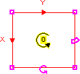
button.Resize
(Rectangle)
If the Bend parameter of the region is set to 0, the region behaves like a rectangle. The height and width of the rectangle (in pixels) are displayed near its center point. When using the mouse, the height and width of the rectangle (in pixels) are displayed in the status bar. The height and width can be altered by the following methods:
Action Keyboard Mouse Reduce width
LEFT ARROW
Click and drag any endpoint boundary
 inward.
Increase width
RIGHT ARROW
Click and drag any endpoint boundary
outward.Reduce height
UP ARROW
Click and drag any endpoint boundary
inward.Increase height
DOWN ARROW
Click and drag any endpoint boundary
outward.Cycle to Rotate mode
F9
N/A
Change region color
SHIFT+F9
N/A
Maximize Cell Region
CTRL+SHIFT+M
On the Job Edit toolbar, click the Maximize Cell Region  button.
Undo an action
CTRL+Z
On the Standard toolbar, click the Undo
button.Redo an action
CTRL+Y
On the Standard toolbar, click the Redo
button.Resize
(Arc Segment)
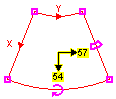
If the Bend parameter of the region is between 0 and 120 (non-inclusive), the region behaves like an arc segment. In this case, the Wide parameter (width) refers to the length of the midpoint arc segment along the Y-axis, and the High parameter (height) refers to the length of the segment along the X-axis. The height and width of the arc-shaped region (in pixels) are displayed near its center point. When using the mouse, the height and width of the arc-shaped region are displayed in the status bar. The height and width can be altered by the following methods:
Action Keyboard Mouse Reduce Y-axis arc length
LEFT ARROW Click and drag any endpoint boundary inward.Increase Y-axis arc length
RIGHT ARROW Click and drag any endpoint boundary outward.Reduce X-axis segment length
UP ARROW Click and drag any endpoint boundary inward.Increase X-axis segment length
DOWN ARROW Click and drag any endpoint boundary outward.Cycle to Rotate mode
F9 N/A Change region color
SHIFT+F9 N/A Maximize Cell Region CTRL+SHIFT+M On the Job Edit toolbar, click the Maximize Cell Region button.Undo an action
CTRL+Z
On the Standard toolbar, click the Undo
button.Redo an action
CTRL+Y
On the Standard toolbar, click tthe Redo
button.Resize
(Circle)
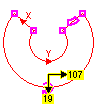
If the Bend parameter of the region is greater than or equal to 120, the region behaves like a circle. In circle mode, you cannot resize both the inner and outer arc lengths simultaneously by using the mouse to drag endpoints; this eases the process of forming a region to a circular object.
In circle mode, the Wide parameter (width) refers to the length of the midpoint arc segment along the Y-axis, and the High parameter (height) refers to the length of the segment along the X-axis. The height and width of the arc-shaped region (in pixels) are displayed near its center point. When using the mouse, the height and width of the arc-shaped region are displayed in the status bar. The height and width can be altered by the following methods:
Action Keyboard Mouse Reduce Y-axis arc lengths (width)
LEFT ARROW
Click and drag any endpoint boundary
inward.Increase Y-axis arc lengths (width)
RIGHT ARROW
Click and drag any endpoint boundary
outward.Reduce X-axis segment length (height)
UP ARROW
Click and drag any endpoint boundary
inward.Increase X-axis segment length (height)
DOWN ARROW
Click and drag any endpoint boundary
outward.Cycle to Rotate mode
F9
N/A
Change region color
SHIFT+F9
N/A
Maximize Cell Region
CTRL+SHIFT+M
On the Job Edit toolbar, click the Maximize Cell Region
button.Undo an action
CTRL+Z
On the Standard toolbar, click the Undo
button.Redo an action
CTRL+Y
On the Standard toolbar, click the Redo
button.Rotate
Adjusts the clockwise or counterclockwise rotation of the region. The angle of rotation (in degrees) is displayed in the center of the region (0 to 360). When using the mouse, the angle of rotation is displayed in the status bar.
Action Keyboard Mouse Rotate clockwise
RIGHT ARROW
Click and drag the rotation
 icon in a clockwise motion.
Rotate counter-clockwise
LEFT ARROW
Click and drag the rotation
icon in a counter-clockwise motion.Cycle to Curve mode
F9
N/A
Change region color
SHIFT+F9
N/A
Undo an action
CTRL+Z
On the Standard toolbar, click the Undo
button.Redo an action
CTRL+Y
On the Standard toolbar, click the Redo
button.Bend
Curves the region upward or downward. Used for creating arc-shaped and annular (circle-shaped) regions.
Action Keyboard Mouse Bend up
LEFT ARROW
Click and drag the curve
 icon upward.
Bend down
RIGHT ARROW
Click and drag the curve
icon downward.Cycle to Move mode
F9
N/A
Change region color
SHIFT+F9
N/A
Undo an action
CTRL+Z
On the Standard toolbar, click the Undo
button.Redo an action
CTRL+Y
On the Standard toolbar, click the Redo
button. Crosses:
Move

Repositions the cross on the image. The pixel coordinates of the center-point of the cross are displayed. When using the mouse, the pixel coordinates are displayed in the status bar.
Action Keyboard Mouse Move left
LEFT ARROW
Click the cross and drag leftward.
Move right
RIGHT ARROW
Click the cross and drag rightward.
Move up
UP ARROW
Click the cross and drag upward.
Move down
DOWN ARROW
Click the cross and drag downward.
Cycle to Resize mode
F9
N/A
Change cross color
SHIFT+F9
N/A
Undo an action
CTRL+Z
On the Standard toolbar, click the Undo
button.Redo an action
CTRL+Y
On the Standard toolbar, click the Redo
button.Resize

Increases or decreases the length of the vertical and horizontal axes of the cross. The length of each axis is shown (in pixels). When using the mouse, the length is displayed in the status bar.
Action Keyboard Mouse Decrease vertical axis
UP ARROW
Click the vertical arrowhead and drag toward the center point of the cross.
Increase vertical axis
DOWN ARROW
Click the vertical arrowhead and drag away from the center point of the cross.
Decrease horizontal axis
LEFT ARROW
Click the horizontal arrowhead and drag toward the center point of the cross.
Increase horizontal axis
RIGHT ARROW
Click the horizontal arrowhead and drag away from the center point of the cross.
Cycle to Rotate mode
F9
N/A
Change cross color
SHIFT+F9
N/A
Undo an action
CTRL+Z
On the Standard toolbar, click the Undo
button.Redo an action
CTRL+Y
On the Standard toolbar, click the Redo
button.Rotate

Adjusts the clockwise or counterclockwise rotation of the cross. The angle of rotation, in degrees, is displayed at the center of the cross (0 to 360). When using the mouse, the angle of rotation is displayed in the status bar.
Action Keyboard Mouse Rotate clockwise
LEFT ARROW
Click and drag the rotation
icon in a clockwise motion.Rotate counter-clockwise
RIGHT ARROW
Click and drag the rotation
icon in a counter-clockwise motion.Cycle to Move mode
F9
N/A
Change cross color
SHIFT+F9
N/A
Undo an action
CTRL+Z
On the Standard toolbar, click the Undo
button.Redo an action
CTRL+Y
On the Standard toolbar, click the Redo
button.Points:
Move

Repositions the point on the image. The pixel coordinates of the point are displayed. When using the mouse, the pixel coordinates are displayed in the status bar.
Action Keyboard Mouse Move left
LEFT ARROW
Click the point and drag leftward.
Move right
RIGHT ARROW
Click the point and drag rightward.
Move up
UP ARROW
Click the point and drag upward.
Move down
DOWN ARROW
Click the point and drag downward.
Change point color
SHIFT+F9
N/A
Undo an action
CTRL+Z
On the Standard toolbar, click the Undo
button.Redo an action
CTRL+Y
On the Standard toolbar, click the Redo
button. Lines:
Set Endpoint(s)

Sets the position of both endpoints of the line. The pixel coordinates of the current endpoint are displayed. When using the mouse, the pixel coordinates are displayed in the status bar.
Action Keyboard Mouse Move endpoint left
LEFT ARROW
Click and drag the endpoint boundary
leftward.Move endpoint right
RIGHT ARROW
Click and drag the endpoint boundary
rightward.Move endpoint up
UP ARROW
Click and drag the endpoint boundary
upward.Move endpoint down
DOWN ARROW
Click and drag the endpoint boundary
downward.Toggle between endpoints
F9
N/A
Change line color
SHIFT+F9
N/A
Undo an action
CTRL+Z
On the Standard toolbar, click the Undo
button.Redo an action
CTRL+Y
On the Standard toolbar, click the Redo
button.
-
If you would like to accept the modifications, then press ENTER. The graphic will appear (in red, by default) over the image, but beneath the semitransparent spreadsheet. To cancel the modifications, press ESC. Once you accept the changes, the new values will automatically be entered into the cell formula or the property sheet value from which interactive graphics mode was accessed.
Interactive Graphics Mode Shortcuts
| Action | Keyboard | Mouse | ||||
|---|---|---|---|---|---|---|
|
Enter interactive graphics mode Note:
In order to enter Interactive Graphics Mode, the active cell or property
sheet value must have an associated interactive graphic.
|
F9 |
|
||||
|
Maximize a region cell graphic. |
N/A |
|
||||
| The following actions are only available while in Interactive Graphics Mode: | ||||||
|
Cycle between interactive graphics modes Note: Depending upon the Interactive Graphics Mode being used, pressing F9 will
cause the icon within the interactive graphic to change.
|
F9 | N/A | ||||
|
Move interactive graphic axially |
|
Click within the interactive graphic and drag to the desired location. | ||||
|
Move interactive graphic diagonally |
|
Click within the interactive graphic and drag to the desired location. | ||||
|
Pan the Image (slowly) |
|
Click and drag the image scroll bars. | ||||
|
Pan the Image (quicker) |
|
Click and drag the image scroll bars. | ||||
|
Zoom in (image) |
SHIFT+PLUS SIGN (on the numeric keypad) |
|
||||
| Zoom out (image) | SHIFT+MINUS SIGN (on the numeric keypad) |
|
||||
| Cycle graphic color. For more information, see Basic Colors. | SHIFT+F9 | N/A | ||||
| Accept changes made to the interactive graphic | ENTER | Double-click
within the interactive graphic, or on the Job
Edit toolbar, click the Enter  button. button. |
||||
| Cancel changes any changes to the interactive graphic | ESC | On the Job
Edit toolbar, click the Cancel  button. button. |
||||
|
Undo an action |
CTRL+Z |
On the Standard toolbar, click
the Undo |
||||
|
Redo an action |
CTRL+Y |
On the Standard toolbar, click
the Redo |
||||
| Display help on Interactive Graphics Mode | F1 | On the Help menu, click In-Sight Explorer Help. | ||||
 button.
  button.
  button.