CC-Link Settings Dialog
The CC-Link Settings dialog configures the active In-Sight vision system for CC-Link communications using a CIO-MICRO-CC I/O module. Input data is read into the spreadsheet using the ReadCCLinkBitBuffer and ReadCCLinkWordBuffer functions. For more information, see ReadCCLinkBitBuffer and ReadCCLinkWordBuffer. Output data is written from the spreadsheet to the CC-Link network using the WriteCCLinkBitBuffer and WriteCCLinkWordBuffer functions. For more information, see WriteCCLinkBitBuffer and WriteCCLinkWordBuffer.
- CC-Link is only available on In-Sight vision systems using In-Sight firmware 4.x.x, and is not available on In-Sight vision systems running In-Sight firmware 5.1.0 and later. For a complete list of models and supported firmware versions, see Firmware Versions.
- Refer to the In-Sight® CIO-MICRO & CIO-MICRO-CC I/O Modules Installation Manual for CC-Link wiring configurations.
Display the CC-Link Settings Dialog
-
On the Sensor menu, click CC-Link Settings.
-
Click the I/O Module button to open the I/O Module Configuration dialog and configure the I/O module. Press the OK button to close the I/O Module Configuration dialog and return to the CC-Link Settings dialog. For more information, see I/O Module Configuration.
Note:- After the first successful connection between the vision system and an I/O module, an "(attached)" message is displayed next to the I/O module that is physically attached to the sensor.
- If CIO-MICRO, CIO-MICRO-CC or CIO-WENET is the selected I/O module, when the OK button is clicked, the vision system attempts to establish EtherNet/IP communication with the module, using the specified IP address. If the IP address does not exist on the network, if EtherNet/IP is not enabled on the module, or if another device already has an EtherNet/IP connection to the module, an error message will appear.
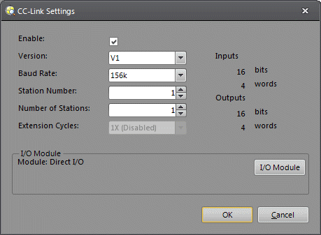
- Configure the CC-Link settings.
CC-Link Settings Dialog Controls
- Version: V1, V2.
- Baud Rate: 10M, 5M, 2.5M, 625K, 156K.
- Station Number: 1 - 64.
- Number of Stations: 1 - 4. If set to 1, Inputs and Outputs are 16 bits. If set to 2, Inputs and Outputs are 48 bits. If set to 3, Inputs and Outputs are 80 bits. If set to 4, Inputs and Outputs are 112 bits.
- Extension Cycles: 1X (Disabled), 2X, 4X, 8X.