ColorToGreyscaleFilter

Available for color In-Sight sensors and color-enabled emulators only, ColorToGreyscaleFilter converts each pixel in a color image or region of interest (ROI) to a greyscale value based on a simple filter of one color parameter: "pure" red, green or blue (RGB); hue, saturation or intensity (HSI); luminance; or interpolation of the weighted average of RGB components. For more information, see Color Components of a Pixel.

Note: Although similar to the GreyscaleDistance function, ColorToGreyscaleFilter offers a more straightforward operation—every output pixel is a function of the selected conversion filter, which focuses on only one component of the pixel (for example, the red value, not the red, green and blue values together, as with GreyscaleDistance). Users might need to experiment with both to determine the best color-conversion function for their applications. For more information on the GreyscaleDistance function, see GreyscaleDistance.

ColorToGreyscaleFilter Inputs

Syntax: ColorToGreyscaleFilter(Image,Fixture.Row,Fixture.Column,Fixture.Theta,Region.X,Region.Y,Region.High,Region.Wide,Region.Angle,Conversion,Show)

Note: The Fixture and Region parameters must be defined within the bounds of the image; otherwise, the function will return #ERR.
Parameter Description

Image

This argument must reference a spreadsheet cell that contains a valid color Image data structure. By default, the cell referenced isA0, the cell containing the Image data structure returned by AcquireImage. For more information, see AcquireImage.

Note: : AcquireImage is the only function that returns a valid color Image data structure.

Fixture

Defines the ROI relative to a Fixture input or the output of a VisionTool function's image coordinate system. Setting the ROI relative to a fixture ensures that if the fixture is rotated or translated, the ROI will be rotated or translated in relation to the fixture.

Note: The default setting is (0,0,0), the top leftmost corner of the image. For more information on Fixture, see Fixture. For more information on VisionTools, see Vision Tools Functions.

Row

Specifies the row offset, in image coordinates.

Column

Specifies the column offset, in image coordinates.

Theta

Specifies the orientation, in image coordinates.

Region

Also known as the region of interest or ROI, specifies the region of the image that undergoes image processing; creates a rectangular image region that can be transformed and rotated. With this parameter selected, clicking the MaximizeRegion button will automatically stretch the region to cover the entire image.

X

Specifies the x-offset of the origin, in fixture coordinates.

Y

Specifies the y-offset of the origin, in fixture coordinates.

High

Specifies the dimension along the region's x-axis.

Wide

Specifies the dimension along the region's y-axis.

Angle

Specifies the orientation, in fixture coordinates.

Conversion

Specifies the type of conversion filter.

Note:
  • Each color pixel is divided into color components.
  • The default color conversion used by other In-Sight tools is equivalent to ColorToGreyscaleFilter's Interpolation conversion filter.

0 = Luminance (default)

Specifies the conversion filter for the luminance of the color. The result is an output image of the luminance. The more light emitted from a pixel in the input image, the lighter its appearance in the output image.

Note:

Luminance is closely related to intensity in concept, and is a measure of the amount of light emitted or reflected from a particular area.

In machine-vision applications, luminance is a greyscale value that is computed from the red, green and blue (RGB) components of a pixel using the following formula:

RGB Luminance value = 0.299xR + 0.587xG + 0.114xB

1 = Red

Specifies the conversion filter for the red component of the color. The result is to filter out all but the red component of the pixel. The higher a pixel's red value in the input image, the lighter its appearance in the output image.

2 = Green

Specifies the conversion filter for the green component of the color. The result is to filter out all but the green component of the pixel. The higher a pixel's green value in the input image, the lighter its appearance in the output image.

3 = Blue

Specifies the conversion filter for the blue component of the color. The result is to filter out all but the blue component of the pixel. The higher a pixel's blue value in the input image, the lighter its appearance in the output image.

4 = Hue

Specifies the conversion filter for the hue component of the color. The result is to filter out all but the hue component of the pixel. The higher a pixel's hue value in the input image, the lighter its appearance in the output image (for example, a red with a hue value of 0 will appear dark).

5 = Saturation

Specifies the conversion filter for the saturation component of the color. The result is to filter out all but the saturation component of the pixel. The higher a pixel's saturation value in the input image, the lighter its appearance in the output image (for example, a white with a saturation value of 0 will appear dark).

6 = Intensity

Specifies the conversion filter for the intensity component of the color. The result is to filter out all but the intensity component of the pixel and to determine the average intensity of the pixel's RGB components. The higher a pixel's intensity value in the input image, the lighter its appearance in the output image (for example, a white with an intensity value of 255 will appear light).

7 = Interpolation

Specifies the conversion filter for the interpolation of the color. As with the Intensity filter, the result is to filter out all but the intensity component of the pixel. The higher a pixel's intensity value in the input image, the lighter its appearance in the output image (for example, a white with an intensity value of 255 will appear light). However, the Interpolation filter determines the weighted average intensity of the RGB components and is a non-standard conversion filter.

Note:

Interpolation is a weighted average of the red, green and blue (RGB) components of a pixel using the following formula:

Interpolation value = 0.25xR + 0.50xG + 0.25xB

Show

Specifies which graphical overlays are displayed on top of the image.

0 = hide all (default)

The input image region will be hidden, except when the cell containing the ColorToGrayscaleFilter function is highlighted in the spreadsheet.

1 = result graphics only

The processed image will be displayed at all times.

2 = input graphics only

The input image region will be displayed at all times.

ColorToGreyscaleFilter Outputs

Returns

An Image data structure containing the processed image, or #ERR if any of the input parameters are invalid. For more information, see Structures.

ColorToGreyscaleFilter Example

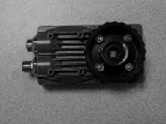
In this example, the object in the input image is a yellow Cognex sensor, which is also used in the example for GreyscaleDistance. Random samplings of the image (achieved by toggling off the Overlay view by choosing Overlay on the View menu, moving the cursor over the sensor and viewing the RGB information in the status bar in the bottom-left corner of the window) reveal RGB values of 205-185-124, 193-177-110, 175-154-39, 133-104-2 and 115-91-6 for the sensor. For more information on GreyscaleDistance, see GreyscaleDistance.

After inserting the function into the In-Sight spreadsheet, the user defines the ROI by double-clicking on the word "Region" in the property sheet, which disappears to reveal the red ROI box overlaid on the image. The user moves or resizes the box using the cursor and clicks the green "checkmark" icon in the In-Sight toolbar (or presses the Enter key on the keyboard) to confirm the selection and return to the property sheet.

Selecting a conversion filter, accepting the default settings of the other parameters and clicking OK in the property sheet completes the configuration for this example and applies the function to the input image.

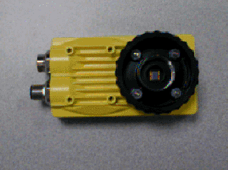
Below are three output images of the red, green and blue filters applied, respectively. As expected, the yellow of the sensor is brightest in the red-filtered image because red is the strongest color component in the yellow sensor.(The maximum red value for the image is 210, the mean is 116 and the median is 127.) The closer the input pixel value is to the filter's value, the brighter the output pixel.

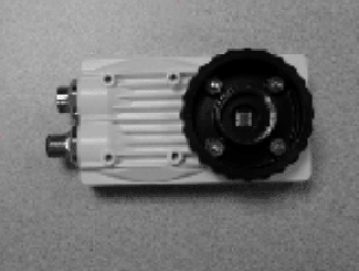
The yellow of the sensor is slightly darker in the green-filtered image because it contains less green (maximum of 199, mean of 112 and median of 125), compared with red.

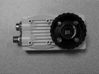
The yellow of the sensor is darkest in the blue-filtered image because it contains little blue (maximum of 197, mean of 101 and median of 121), compared with red.