InspectEdge
The InspectEdge function is used to perform advanced edge analysis. Within the function's referenced Region of Interest (ROI), an array of indexed, edge detecting sub-regions (called Calipers) develop detailed information about the precise location of features, by locating edges or edge pairs in an image. This information is used to determine the location of edges or features, the location and spacing of pairs of edges, and measure the width of objects in images.
InspectEdge Overview
After inserting the InspectEdge function, the ROI is established, either using the function's own internal region or as a reference to an external ROI, such as an EditMaskedRegion or EditPolylinePath, to determine where in the image the tool should detect the edge or edge pairs. For more information, see EditMaskedRegion or EditPolylinePath. The referenced ROI is segmented into individual Calipers, where each Caliper projects the pixels within it into a single convolution for edge analysis.
Once the ROI has been configured, the following steps are necessary to properly apply the function:
- Specify Caliper, Minimum Contrast and Edge Width parameter values that isolate the edges of interest
- Define an edge model that describe the edge or edge pair of interest using the InspectEdgeForDefect, InspectEdgePosition, and/or InspectEdgeWidth functions. For more information, see InspectEdgeForDefect, InspectEdgePosition, or InspectEdgeWidth.
With the InspectEdge function in place, multiple inspections can be performed using a single InspectEdge function as an input. For example, within one InspectEdge ROI, an InspectEdgeForDefect function could reference the function to determine positional defects, while an InspectEdgeWidth function performs a separate width measurement, and an InspectEdgePosition function determines a best-fit line for another edge.
InspectEdge Inputs
Syntax: InspectEdge(Image,Fixture.Row,Fixture.Column,Fixture.Theta,Region.X,Region.Y,Region.High,Region.Wide,Region.Angle,Region.Curve,External Region or Path,Caliper.Height,Caliper.Repeat Offset,Caliper.Initial Offset,Minimum Contrast,Edge Width,Fit All Calipers,Caliper Graph Index,Polyline Width,Show)
| Parameter | Description | ||||||||||||
|---|---|---|---|---|---|---|---|---|---|---|---|---|---|
|
Specifies a reference to a spreadsheet cell that contains an Image data structure; by default, this parameter references A0, the cell containing the AcquireImage Image data structure. This parameter can also reference other Image data structures, such as those returned by the Vision Tool Image functions or Coordinate Transforms Functions. |
|||||||||||||
|
Defines the Region of Interest (ROI) relative to a Fixture input or the output of a Vision Tool function's image coordinate system. Setting the ROI relative to a Fixture ensures that if the Fixture is rotated or translated, the ROI will be rotated or translated in relation to the Fixture. For more information, see Fixture and Vision Tools Functions. Note: The default setting is (0,0,0), the top leftmost
corner of the image.
|
|||||||||||||
|
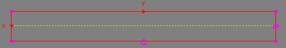
Also known as the Region of Interest (ROI), specifies the region of the image that undergoes edge analysis; creates a rectangular image region that can be transformed and rotated. With this parameter selected, by pressing the Maximize Region button on the property sheet's toolbar, the region will automatically be stretched to cover the entire image. The dashed yellow line indicates the direction in which the edge will be found.
|
|||||||||||||
|
Specifies a reference to a spreadsheet cell that contains an Annulus, a Region, an EditAnnulus, an EditMaskedRegion, an EditPolylinePath or an EditRegion function. When this parameter is used, the function ignores the Region and Fixture settings and inspects the image area specified by the referenced region. Note:
|
|||||||||||||
|
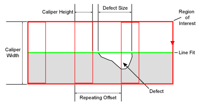
Specifies the Caliper array within the ROI that will be used to define the size of the detectable defects and/or gaps. The size of the detectable defect or gap is determined by the number of edges that can be detected, which is determined by the number of Calipers placed along the edge. The Calipers are displayed within the ROI as red rectangles, and edges detected within the Caliper are displayed in green, when the InspectEdge cell is highlighted or the Show parameter is set to show all. Note: Depending on the type of defect being examined, Calipers may be positioned to overlap. However, the more Calipers that are applied within the ROI will increase the function's execution time.
|
|||||||||||||
|
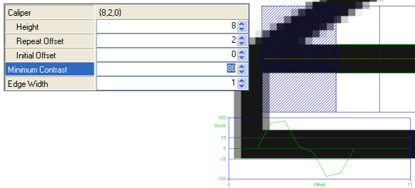
Specifies the minimum greyscale contrast transition (0 to 255; default = 5) to be considered an edge. For each indexed Caliper, a contrast graph, drawn in blue, is displayed on the image. The values in the chart are automatically scaled to a 0-100 value. Utilize this chart when applying this parameter to properly adjust the value. |
|||||||||||||
|
Specifies the pixel distance (1 to the Region width value; default = 3) over which an edge transition takes place. This setting is the approximate size of the pixel operator used to filter the greyscale projections before edges are extracted; use this setting to filter noise from the image. |
|||||||||||||
|
Specifies whether or not all of the Calipers are placed within the ROI.
|
|||||||||||||
|
Specifies the Caliper to be displayed on the image (the Caliper will be outlined in green); default Caliper displayed is 0. |
|||||||||||||
|
Specifies the height (1 to Region height value; default = 20) of an EditPolylinePath. |
|||||||||||||
|
Specifies the display mode for InspectEdge graphical overlays on top of the image.
|
InspectEdge Outputs
|
Returns |
An Inspect data structure containing the detected edges in the image and the number of Calipers, or #ERR if any of the input parameters are invalid. |
|
The number of Calipers in the ROI. |