PointFilter
A multipurpose function, PointFilter produces a black-and-white or greyscale output image where every pixel is the result of a "global" image-enhancement technique - for example, thresholding, inversion, histogram equalization or greyscale stretching or clipping - applied to each pixel in the input image or region of interest (ROI).
- This function is only available on In-Sight vision systems running In-Sight firmware 4.x.x, and is not available on In-Sight vision systems running In-Sight firmware 5.1.0 and later. For a complete list of models and supported firmware versions, see Firmware Versions.
- In-Sight vision systems running In-Sight firmware 5.1.0 and later have had this function consolidated into the Filter function. For more information, see Filter.
- If attempting to load a job containing the PointFilter or NeighborFilter functions to an In-Sight vision system running In-Sight 5.1.x firmware, and the function is password-protected using the Format Cells dialog’s Protection tab, the job load will fail. Load the job to an In-Sight vision system running In-Sight firmware 4.x.x and modify the job. For more information on accessing or removing password-protected cells, see Licensing.
PointFilter Inputs
Syntax: PointFilter(Image,Fixture.Row,Fixture.Column,Fixture.Theta,Region.X,Region.Y,Region.High,Region.Wide,Region.Angle,Operation,Minimum,Maximum,Threshold,Show)
| Parameter | Description | ||||||||||||||||
|---|---|---|---|---|---|---|---|---|---|---|---|---|---|---|---|---|---|
|
This argument must reference a spreadsheet cell that contains a valid Image data structure. By default, the cell referenced is A0, which contains the Image data structure returned by AcquireImage. For more information, see AcquireImage. |
|||||||||||||||||
|
Defines the ROI relative to a Fixture input or the output of a Vision Tool function's image coordinate system. Setting the ROI relative to a fixture ensures that if the fixture is rotated or translated, the ROI will be rotated or translated in relation to the fixture. Note: The default setting is (0,0,0), the top leftmost
corner of the image. For more information, see Fixture or Vision Tools Functions.
|
|||||||||||||||||
|
Also known as the region of interest or ROI, specifies the region of the image that undergoes image processing; creates a rectangular image region that can be transformed and rotated. With this parameter selected, clicking the Maximize Region button will automatically stretch the region to cover the entire image.
|
|||||||||||||||||
|
Specifies the "pixel-by-pixel" image-processing operation that will produce a greyscale or black-and-white output image. Note: Parameters
not applicable to the selected operation are dimmed or "greyed-out."
|
|||||||||||||||||
|
Specifies the minimum greyscale value (0–255; default = 0) for the Clip and Threshold Range operations. |
|||||||||||||||||
|
Specifies the maximum greyscale value (0–255; default = 255) for the Clip and Threshold Range operations. |
|||||||||||||||||
|
Specifies the threshold levels for the Binarize and Greyscale Distance operations.
|
|||||||||||||||||
|
Specifies which graphical overlays are displayed on top of the image.
|
PointFilter Outputs
|
Returns |
An Image data structure containing the processed image, or #ERR if any of the input parameters are invalid. |
PointFilter Example
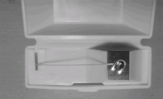
In this example, various filters from PointFilter are applied to enhance the input image of a container of dental floss (below).
After inserting PointFilter into the spreadsheet, the user defines the ROI by double-clicking on the word "Region" in the property sheet, which disappears to reveal the red ROI box overlaid on the image. The user moves or resizes the box using the cursor, and clicks the OK  button on the Job
Edit toolbar to confirm the selection and return to the property sheet. (The selection can also be confirmed by pressing the Enter key or by double-clicking within the ROI.)
button on the Job
Edit toolbar to confirm the selection and return to the property sheet. (The selection can also be confirmed by pressing the Enter key or by double-clicking within the ROI.)
Selecting a filter from the Operation pull-down menu, accepting the default settings of the other parameters and clicking OK in the property sheet completes the configuration for this example and applies the function to the input image.
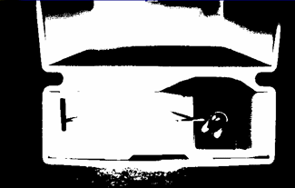
Below is the output image produced by the Binarize operation. All input pixel values equal to or above the user-set threshold are displayed as white; all values below the threshold are black.
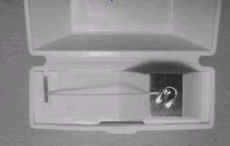
Below is the output image produced by the Clip operation. The minimum and maximum values are set at 40 and 125, respectively. Compared with the input image, the output image below displays slightly decreased contrast, while still differentiating the object from its background. This operation is useful if glare or bright areas in the image make it difficult to extract the desired data.
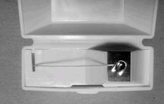
Below is the output image produced by the Stretch operation, which is the opposite of the Clip operation. The minimum and maximum are scaled to the full greyscale range, with values of 0 and 255, respectively. As a result, the output image displays greater contrast than the input image.
For more information, see Property Sheet, Image, or Image.