SurfaceFX
The SurfaceFX function performs feature enhancement, utilizing lighting to create a high contrast image which enhances three dimensional features on an object, for feature extraction and inspection by other Vision Tools.
The function removes noise and/or clutter from the surface's background, isolating surface features that are engraved, embossed, stamped, etched, recessed or raised, as well as defects (such as chips, dents, wrinkles, punctures and tears). Once a contrast image is generated, other Vision Tools (such as OCRMax, TrainPatMaxRedLine and FindPatMaxRedLine, DetectBlobs, SurfaceFlaw and InspectEdge) can be used for inspections and defect detection.
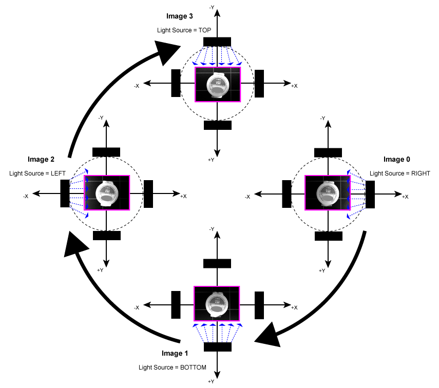
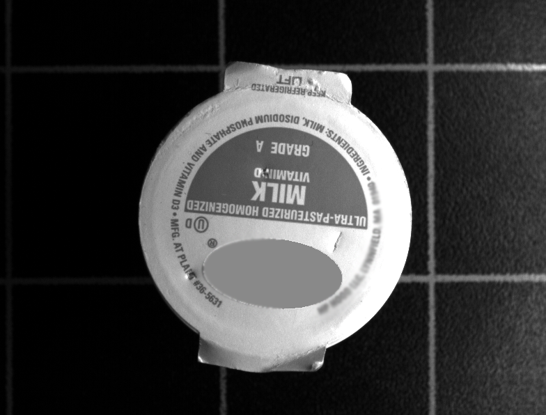
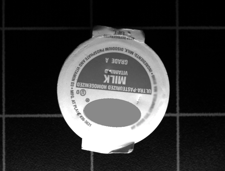
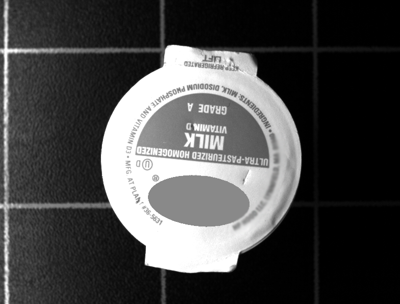
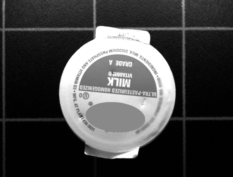
The SurfaceFX algorithm requires four images to be acquired, in sequence, from four individual, low angular (less than 45°) light sources. The light sources should be spaced evenly around the circumference of a circle, with the object placed under the center of the lights. During the acquisition phase, the object should remain stationary, and the lighting and image acquisition sequence must be clockwise; starting from the right quadrant of the object, followed by the bottom quadrant, then the left quadrant, and finally the top quadrant.
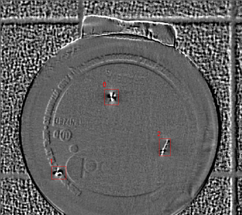
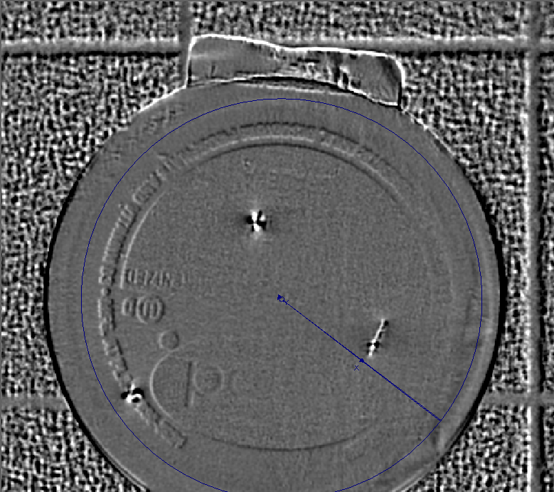
The algorithm will then produce a surface irregularity image, with the raised features displayed in white, and indented features displayed in black.
SurfaceFX Inputs
Syntax: SurfaceFX(Right,Bottom,Left,Top,Sigma,Brightness,Contrast,Show)
|
These arguments must reference a spreadsheet cell that contains a valid Image or LatchImage data structure, with low angular (less than 45°) lighting from the right, bottom, left or top of the object.
Note:
|
|||||
|
Specifies the smoothness value (0–10; default = 1) to help eliminate high-frequency noise in the output image. |
|||||
|
Specifies the average intensity (0–255; default = 128) of the background in the output image. |
|||||
|
Specifies the intensity difference (0–100; default = 10) between surface features and the background pixels in the output image. |
|||||
|
Specifies which graphical overlays are displayed on top of the image.
|
SurfaceFX Outputs
|
Returns |
An Image data structure containing the processed surface irregularity image, or #ERR if any of the input parameters are invalid. |
SurfaceFX Example
In this example, the goal is to use the SurfaceFX function to generate an output image with enhanced surface features that will be passed to a SurfaceFlaw function for further inspection. SurfaceFX requires external light sources, with a control over the light sources, to combine the lighting and image acquisition sequence. Each image should have low angular (less than 45°) lighting coming from a single quadrant of the image plane (right, bottom, left and top). As each quadrant is illuminated, an image should be acquired. Once all four images are acquired, the images can be passed into the SurfaceFX function. These images can be stored via disabling cells or using latched images.
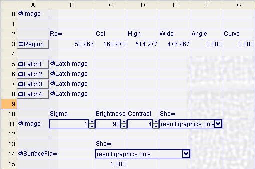
- This example uses four LatchImage functions that have the Event parameter set to a corresponding Button function (Latch1, Latch2, Latch3, Latch4). For more information, see LatchImage and Button.
- Their Region parameter shares a common EditRegion function, so that each image passed into the SurfaceFX function will have the same shape and orientation. For more information, see EditRegion.
- The images stored by the LatchImage functions are acquired with lighting from the four different directions (right, bottom, left and top) and then passed to a SurfaceFX function (A11).
- A SurfaceFlaw function with the Image parameter referencing the Image data structure output by the SurfaceFX function performs the inspection of the object. For more information, see SurfaceFlaw
-
For the first image, lighting from the right side is activated and an image is acquired. The Latch1 Button (cell A5) is then pressed to store the acquired image in the LatchImage cell at B5.
-
For the second image, lighting from the bottom side is activated and an image is acquired. The Latch2 Button (cell A6) is then pressed to store the acquired image in the LatchImage cell at B6.
-
For the third image, lighting from the left side is activated and an image is acquired. The Latch3 Button (cell A7) is then pressed to store the acquired image in the LatchImage cell at B7.
-
For fourth image, lighting from the top side is activated and an image is acquired. The Latch4 Button (cell A8) is then pressed to store the acquired image in the LatchImage cell at B8.
-
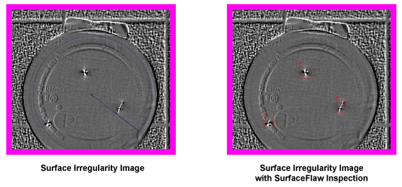
The SurfaceFX function then runs based on the four LatchImage data structures as input images, generating an output image with enhanced features that highlight indentations on the surface (below).
-
Finally, the SurfaceFlaw function uses the SurfaceFX output image as its input image, detecting areas of local intensity and size variations to identify flaws in the image (below).