InspectEdgePosition

The InspectEdgePosition function is used to construct an edge model to perform advanced edge analysis on the edges returned by an InspectEdge function. This data is used determine the location of edges, identifying outlier edges, and optionally constructing a line fit.

InspectEdgePosition Overview

After inserting the function into the spreadsheet, a reference must be made to an Inspect data structure output by an InspectEdge function. Once the reference to the InspectEdge function has been established, the edge model is created by configuring the parameters of the InspectEdgePosition function. The edge model involves defining the following:

  • The type of line fit - straight or circular.
  • The direction in which to detect edges.
  • The type of edge transition - white to black or vice-versa.
  • The edge scoring criteria that will be used to filter unwanted edges.
  • The line fit criteria that will be used to filter unwanted edges from the line fit.

Once the edge model has been established, the function will compare edge candidates against the edge model and report deviations from the model.

InspectEdgePosition Inputs

Parameter Description

InspectEdge

Specifies a reference to a spreadsheet cell that contains a valid Inspect data structure returned by an InspectEdge function.

Line Fit

Specifies the type of line fit to be constructed out of the detected edges.
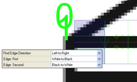
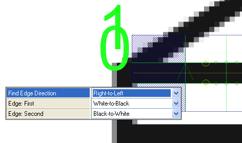
0 = None

The function will not create a line fit. The position of found edges is measured relative to the center of the ROI.

1 = Straight Line Fit

The position of found edges is measured relative to the line fit.

2 = Circle Line Fit

The function will create a circular line fit from the detected edges.

3 = Auto Fit (default)

The function automatically creates either a straight line or circular fit, based on the referenced Region.

4 = Region

The function will not create a line fit. The position of found edges is measured relative to the center of the ROI.

Find Edge Direction

Specifies the direction in which the function will attempt to detect edges. Dark green arrows are added to graphically illustrate the direction in which the edge will be detected. Fit lines will be labeled graphically within the image, with the first fit line being labeled 0, and the second fit line being 1.

Note: If the region of interest (ROI) of the referenced InspectEdge function is bent into a curve, the inspection will be relative to the curve’s center. When the Find Edge Direction parameter is set to Left-to-Right, it inspects towards the curve’s center, and when set to Right-to-Left, it inspects away from the curve’s center.

0 = Left-to-Right (default)

The function will attempt to detect edges from the left of the ROI to the right.


Example

1 = Right-to-Left

The function will attempt to detect edges from the right of the ROI to the left.


Example

Edge: First

Specifies the contrast transition of the first edge to be detected, as determined by the Find Edge Direction parameter.

1 = Black-to-White

The edge transitions from black pixels to white pixels.

2 = White-to-Black (default)

The edge transitions from white pixels to black pixels.

3 = Either

The edge can transition from either black-to-white, or white-to-black, and the function will determine the proper transition. Specifying the transition improves the performance of the function.

Edge Scoring

Specifies the edge scoring mode that will be used to determine whether or not an edge meets the established criteria.

Score Threshold

Specifies a scoring threshold to filter out edges with scores (1 to 100; default = 10) lower than this value.

Edge Rules

Specifies the type of edge that is most important when calculating the score.

1 = First

The first edge detected receives the highest consideration.

2 = Strongest

The edge with the strongest contrast transition receives the highest consideration.

3 = First Strongest (default)

The first edge detected, with the strongest transition, receives the highest consideration.

Contrast Upper Bound

Specifies the upper limit of the edge contrast transition (2 to 255; default = 255) to be considered an edge; edges with an edge contrast transition above this value will have the same highest score.

Advanced Line Fit

Specifies how the function should construct the line fit.

Filter Outliers

Specifies that the function will remove points from the Fit Line that are further than the distance specified in the Fit Distance Filter parameter.

0 = Off (default)

The function will not account for outlier edges.

1 = On

The function will account for outlier edges in its calculation.

Fit Distance Filter

Specifies the distance, in pixels (valid ranges are 1 to 3 times the In-Sight vision system's image width; default = 2), from which an edge must be from the original Fit Line to be utilized in a re-fit calculation. This setting is useful in helping to prevent defects from affecting the line fit. Filter Outliers must be On to enable this setting.

Furthest Point Filter Distance

Specifies the distance an outlier can be from the line fit and still considered a part of the line fit (valid ranges are 1 to 3 times the In-Sight vision system's image width; default is 3 times the vision system's image width); any edge which is greater than this value will be ignored.

Re-Score

Specifies that the edges will be re-scored to select edges which are closer to the line fit.

0 = Off (default)

The function will not re-score the edges to account for outliers.

1 = On

The function will re-score the edges to account for outlier edges in its calculation.

Re-Fit

Specifies that the function will re-fit the line fit after the edges have been re-scored. Enabling this functionality helps the accuracy of the line fit, however it adds processing time.

0 = Off (default)

The function will not attempt to re-fit the line fit.

1 = On

The function will re-fit the line fit after the edges have been re-scored.

Caliper Index

Specifies the Caliper to be displayed on the image (the Caliper will be outlined in green); default Caliper displayed is 0.

Show

Specifies the display mode for InspectEdgePosition graphical overlays on top of the image.

0 = hide all (default)

All graphics will be hidden, except when the cell containing the InspectEdgePosition function is highlighted in the spreadsheet.

1 = result graphics only

The line fit, detected defects, outlier points and/or gaps will be displayed at all times.

2 = result graphics and caliper detail

The line fit, detected defects, outlier points and/or gaps, detected edge points, and the indexed Caliper window will be displayed at all times.

3 = show all: input and result graphics

Both the input region, line fit, detected defects, outlier points and/or gaps, and detected edge points will be displayed at all times.

InspectEdgePosition Outputs

Returns

An Inspect data structure containing the matching edges sorted by score, or #ERR if any of the input parameters are invalid.

Results

When InspectEdgePosition is initially inserted into a cell, a results table is created in the spreadsheet using the following InspectEdge Vision Data Access Functions The InspectEdgePosition data structure result table, which is broken into two sections, Furthest Points and Straight Line Fit:

Spreadsheet Name

Function Name

Description

Furthest Points
Point 1/Point 2 GetExtremePosPoints(Inspect, Side) Returns the index of the Caliper whose edge is furthest from the line fit on either side (Near = 0 and Far = 1), or, if the Line Fit is set to None, returns the points nearest either edge of the Region.
X GetEdgePosX(Inspect, Caliper Index, Edge Index) Returns the x-coordinate of the specified Caliper's edge index position (Point 1).
Y GetEdgePosY(Inspect, Caliper Index, Edge Index) Returns the y-coordinate of the specified Caliper's edge index position (Point 2).
Straight Line Fit
X0 / Y1 GetFitEdgePosX(Inspect, Point Index) Returns the x-coordinate of the specified point of the line fit.
Y0 / Y1 GetFitEdgePosY(Inspect, Point Index) Returns the y-coordinate of the specified point of the line fit.
Center X GetFitEdgePosCenterX(Inspect, Point Index) Inserted when a Circle Line Fit is specified, returns the x-coordinate of the center of the circle line fit.
Center Y GetFitEdgePosCenterY(Inspect, Point Index) Inserted when a Circle Line Fit is specified, returns the y-coordinate of the center of the circle line fit.
Radius GetFitEdgePosRadius(Inspect, Point Index) Inserted when a Circle Line Fit is specified, returns the distance from the center of the circle line fit.

All of the formulas for the InspectEdgePosition conform to the following:

Note:
  • Inspect = An Inspect data structure output by an InspectEdgePosition function
  • Caliper Index = 0 to N (the total number of Calipers is equal to the number of Calipers output by the InspectEdge function that the InspectEdgeForDefect function is referencing)
  • Edge Pair Index = 0 or 1
  • Edge Index = 0 to N
  • Point Index = 0 to 1 (0 = Start and 1 = End)