
Answer
Table of Contents
1 Configuration in In-Sight Explorer
2 Configuration on TIA Portal
3 Communication
3.1 Image Acquisition
3.2 Job Change
3.3 Data Transfer
4 Resources
1 Configuration in In-Sight Explorer
1.1 Start In-Sight Explorer.
1.2 Connect the camera.
1.3 Activate "PROFINET" under Menu -> Sensor -> Network Settings -> Industrial Ethernet Protocols.
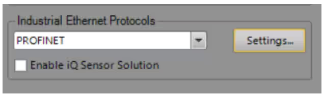
1.4 Optional: Assign Profinet name (no capital letters)
2 Configuration on TIA Portal
2.1 Open TIA Portal and create a new project.
2.2 Add the PLC to the project:
_ Click on "Add new device" -> Select PLC type.
_ Double-click on “Devices & Networks” -> Network view.
_ Click on PLC CPU icon -> General -> PROFINET
_ Enter IP address for the CPU.
2.3 Add the camera to the project
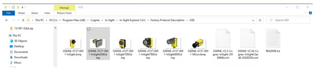
_ If GSD file already exists -> import camera from catalog.
_ Otherwise -> Upload GSD file: Menu -> Options -> Manage GSD ... -> select path -> select GSD file -> install
_ Firmware < 5.8 -> GSD v2.3; Firmware >= 5.8 -> GSD v2.34
_ Set IP of the camera: preferable "IP is set directly at device “.
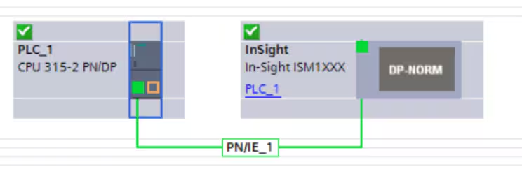
2.4 Connecting PLC and camera
2.5 Load project on PLC
2.6 Go online and check connection status.
2.7 Set start addresses:
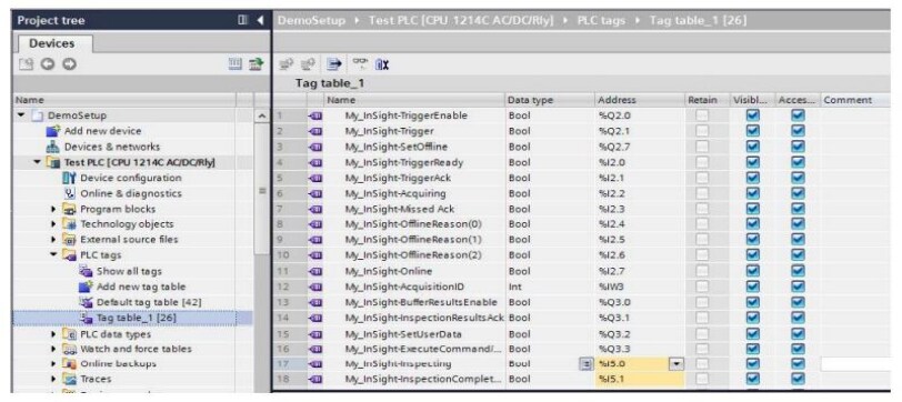
Copy start addresses from the Device Overview and paste them into the Tag Generator.
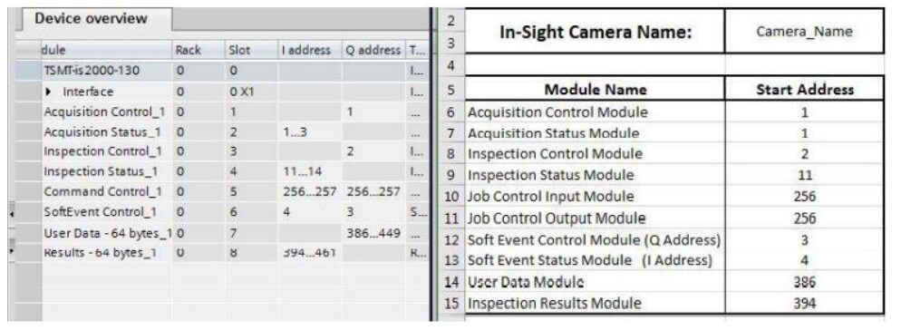
Then copy all generated addresses from the Tag Generator and paste them into PLC Tags & Watch Tables.
3 Communication
3.1 Image Acquisition
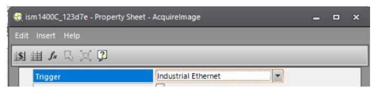
In In-Sight Explorer (ISE) -> cell A0 (Acquire Image function) -> Trigger Mode = Industrial Ethernet
Camera Online.
Set "Trigger Enable" bit.
Set "Trigger" bit.
3.2 Job Change
Job Change by ID:
Camera Offline.
Write the job-ID to "Command" of the Command Control Input.
Set AND hold "Execute Command" bit.
Wait for "Command Complete" or "Command Failed".
Job must exist on the camera.
Job Change by Name is documented in ISE Help.
3.3 Data Transfer
Camera Online.
Camera to PLC: %I address
TIA Portal: Inspection Status Module, Inspection Results Module.
ISE FW 4.x.x: FormatOutputBuffer + WriteProfinetBuffer.
ISE FW 5.x.x: FormatOutputBuffer + WriteResultsBuffer
PLC to camera: %Q address
TIA Portal: Inspection Control Module, Soft Event, User Data.
ISE FW 4.x.x: FormatInputBuffer + ReadProfinetBuffer. • ISE FW 5.x.x: FormatInputBuffer + ReadUserDataBuffer.
Enable User Data Bypass OR set SetUserData Bit
4 Resources
Online ISE-Documentation: In-Sight® Explorer Help - PROFINET Communications - Documentation | Cognex
Tag Generator:
https://support.cognex.com/en/resources/integration-guide/cognex-profinet-tag-generator/english/FpDOQZZpSaaenlUOCWPgQg