Details
The SLMP Protocol uses standard Ethernet hardware and software to exchange I/O data, alarms, and diagnostics. It is Mitsubishi Electric’s publicly available, standardized communication format for communicating with Q, iQ and FX Series PLCs through Ethernet or serial connections. In-Sight Vision Suite (ISVS) supports SLMP Protocol on Ethernet only. The abbreviation for SeamLess Message Protocol.
In-Sight Vision Suite settings:
- Set Camera IP in range with PLC.
- Open Industrial Ethernet Configuration settings.
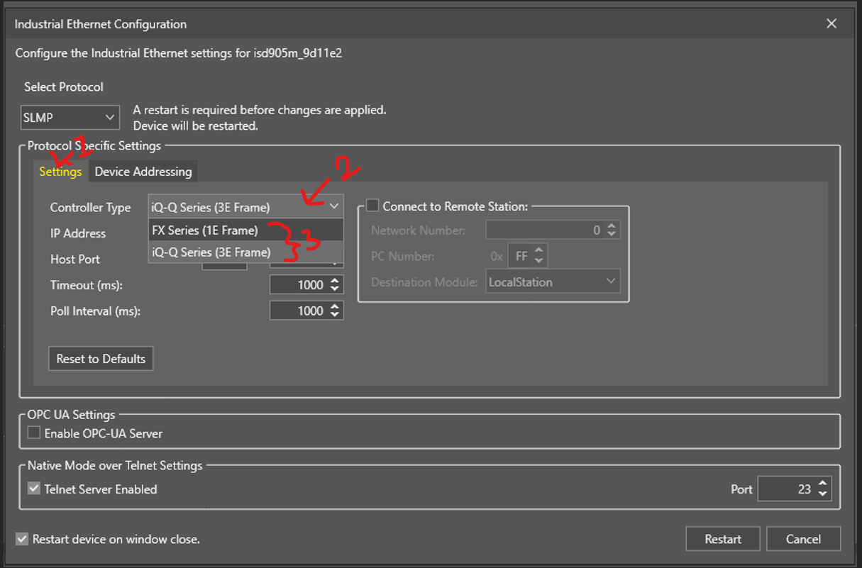
- In Industrial ethernet configuration select protocol as SLMP.
Under Protocol Specific settings Select controller type as per your PLC series. (FX or iQ Q)
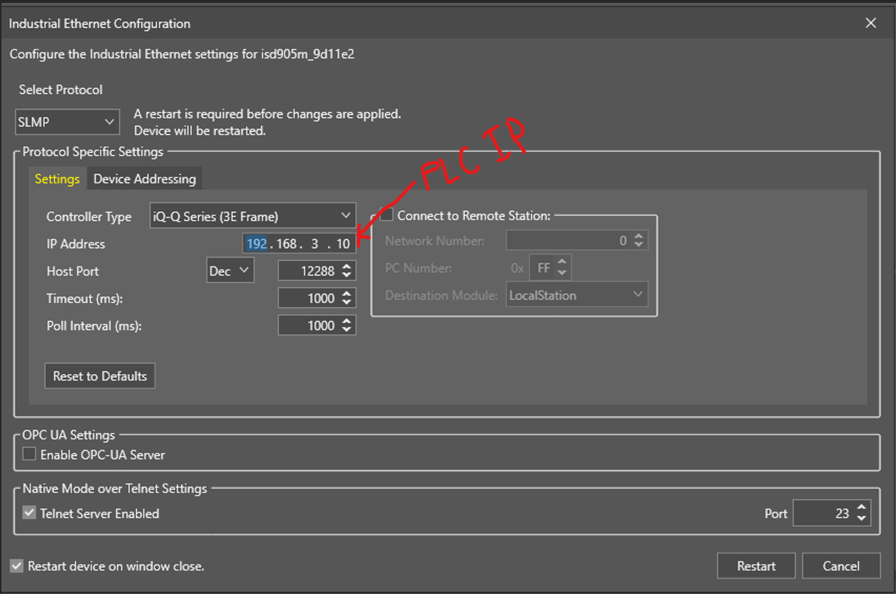
Set IP address of the PLC Device.
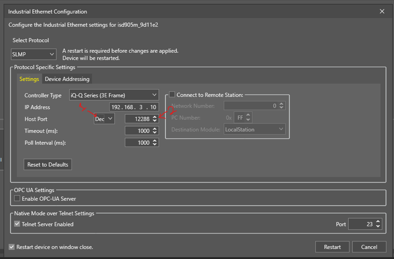
Select the Host port to DEC/ 12288.
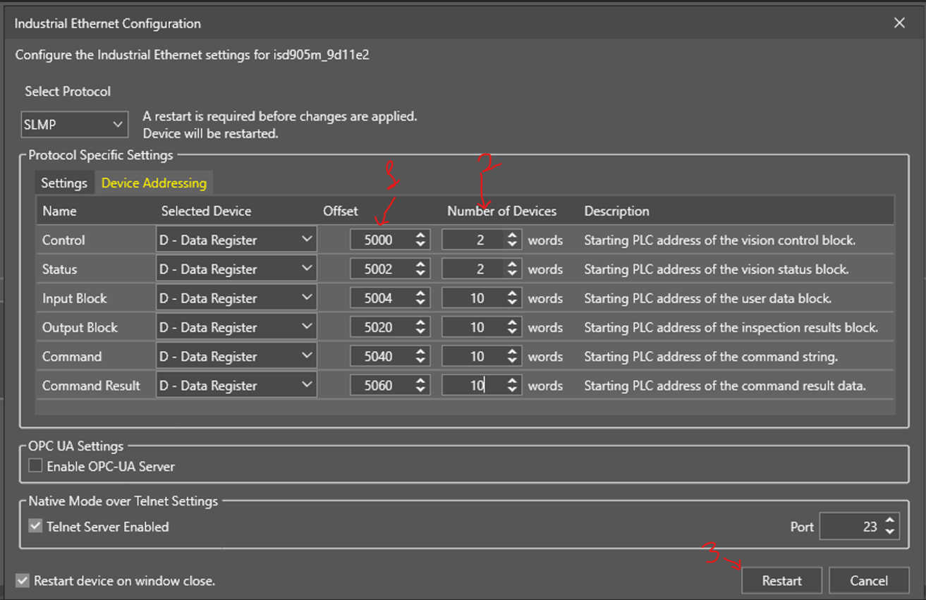
Select Device addressing.
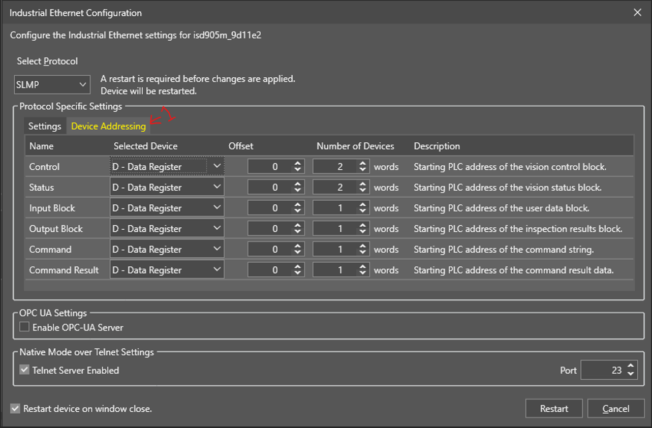
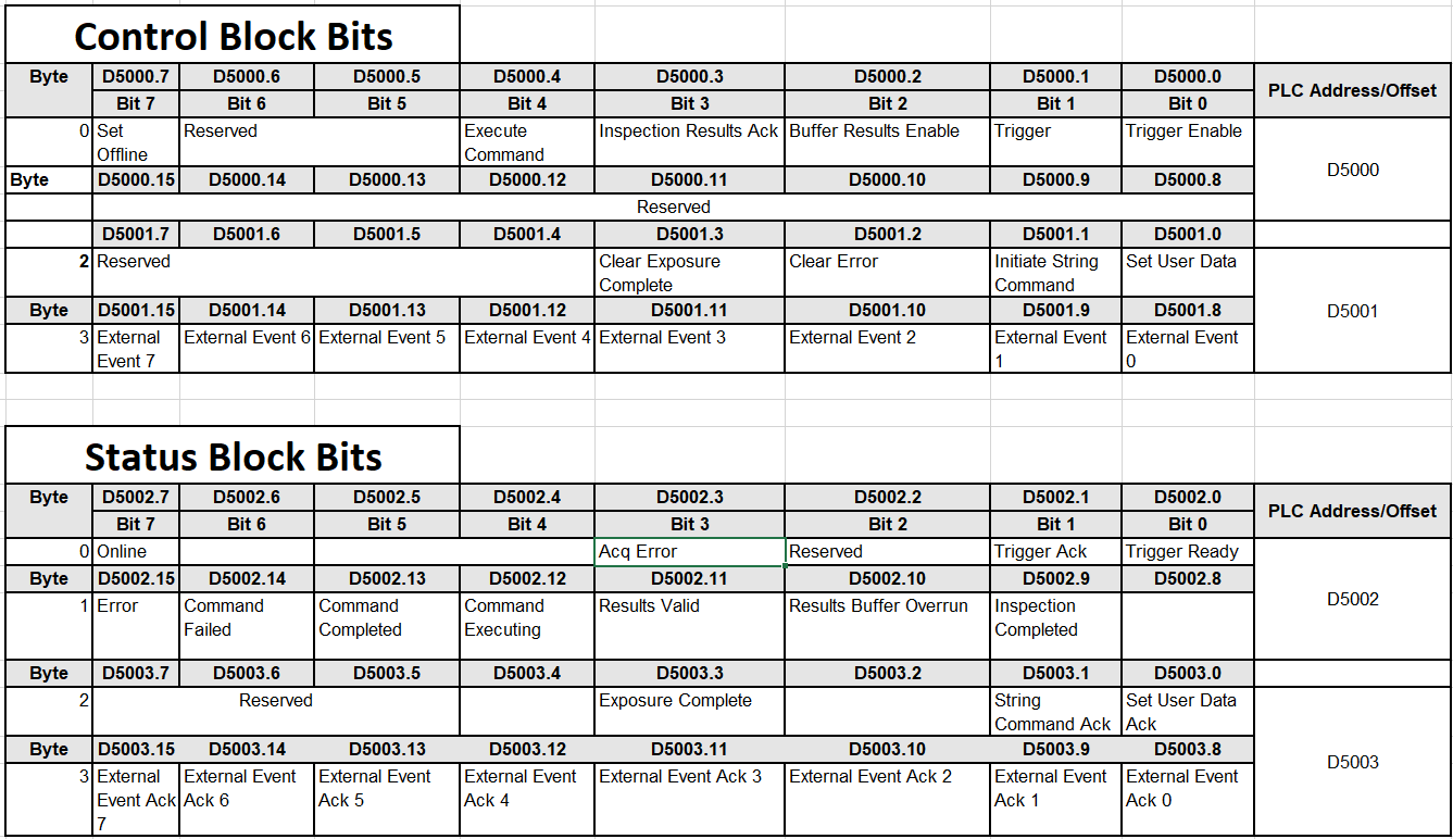
In device addressing we need to set the data address for SLMP Defined Data Blocks. defined data blocks allow you to control where the vision system is reading and writing data to and from the Automation Controller. For easier application setup, the various control and status bits required for command functionality are grouped into contiguous blocks, which can be processed together. When setting up the interaction between the vision system and the Automation Controller, you need to choose the starting address and device type for each block of data. Here for example we set the D register and offset select accordingly to the Word size.
Word size for control block is 2 Bytes.
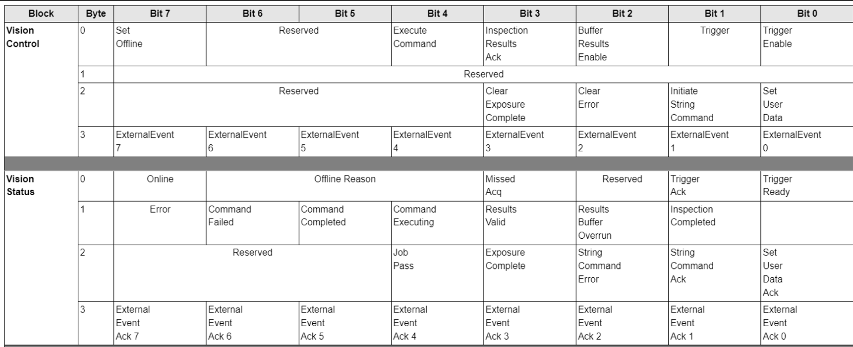
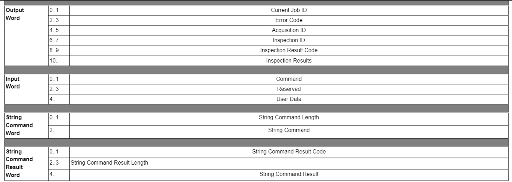
-
- Set the offset as same as the register address in PLC.
- Number of data register it will use in memory.
Please Restart the ISVS.
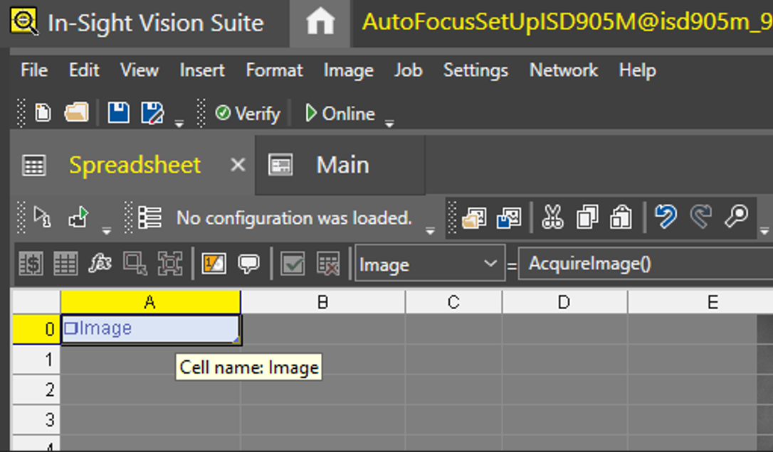
Open the spreadsheet and open the image setting by double clicking.
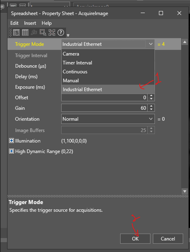
Select the Trigger setting to “Industrial Ethernet”. And put camera in “Online Mode”.
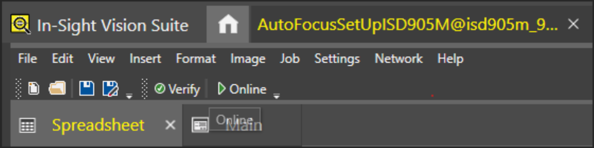
Put camera in online mode.
PLC side settings FXUC
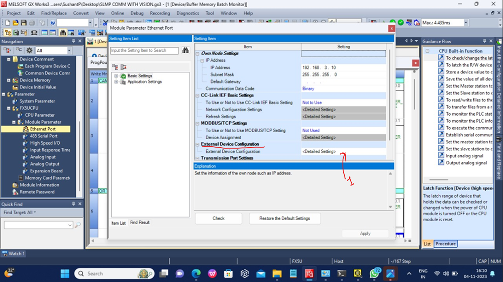
Parameter-> FX5UCPU - > Module Parameter -> Ethernet Port.
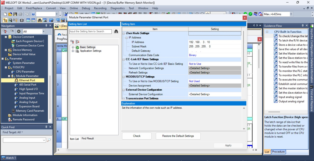
Open External device configuration.
Drag and drop the SLMP connection module from module list.
Module List -> Ethernet device (general) -> SLMP connection module
Set the port number as 12288.
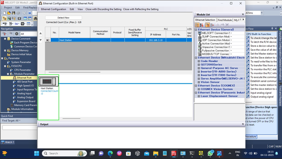
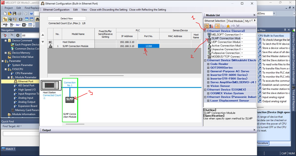
Close with reflecting setting -> Check -> Apply
Ladder program.
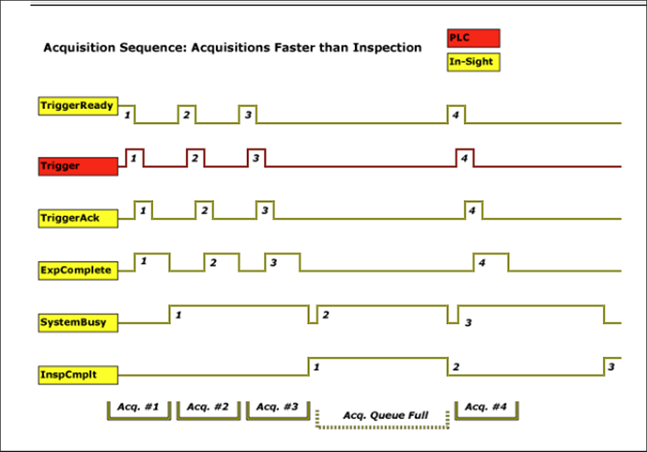
when the following conditions are met:
- The In-Sight vision system is Online.
- The Trigger Enable bit is set.
- The Trigger parameter is set to Network, External or Industrial Ethernet.
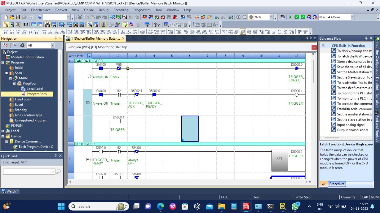
Example address bits.