Supervised Mode – Labeling Defects
When the Red Analyze tool is in Focused Supervised Mode, you have to first identify the defects in the Views, and then carefully label the defects by graphically drawing defect regions over them.
-
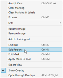
To label defects, right-click within the View and select Edit Region from the menu.
-
This will launch the Edit Regions toolbar at the top of the image.
Default Edit Regions toolbar:

Expert Mode Edit Regions toolbar:
 Note: The Edit Regions toolbar is the same as the Edit Masks toolbar. For more information about the functionality of the buttons in the toolbar, see the Masks topic.
 -
There are three drawing tools, and they can be used in conjunction. The size of the area drawn is defined by the Width value.
-
Line: Click and drag to create a line in your image.
Tip:- Hold down the Shift key while drawing, and the tool will draw a straight line between two points.
- If you want to fill in a rectangular area, draw the outline using the line drawing tool (hold down the Shift key to create straight lines), and then fill it in using the magic wand tool.
-
Circle: Place the cursor at the center of your circular object, and drag outward.
Tip: Hold down the Shift key to have the circle expand from the corner of a bounding box. - Magic Wand: Click and drag to fill in areas of the image. You can also click on individual features to apply fill to just that area.
Note: The Eraser tool can be used to trim and/or remove extraneous drawings on the image.When drawing Regions around the defects, try and draw the Region as precisely and consistently as possible. While drawing small amounts of the Region outside of the defect is acceptable, larger areas should be avoided. This can result in the tool thinking that the background has been labeled as defect. Likewise, under filling a defect should also be avoided.
The graphics below illustrate the best methods for drawing Regions around a defect, where the dark grey lines represent the defect, and the red is the Region defining the defect.
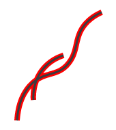

This is the ideal way to draw the Region, with it closely aligned to the defect.
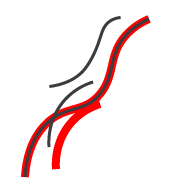
This method encompasses too much of the background, and will result in the tool considering the background as a defect, as well.
This method missed parts of the defect, so the tool will consider the parts not outlined in red as not being a defect.
-
- Once you have carefully and accurately drawn your defect Region, press the Apply button. You must do this on an image-by-image basis.
- Once you have drawn all the necessary Regions, press the Close button prior to training the tool.