Establish the Connection Using a Generic ETHERNET-MODULE
This topic covers integrating In-Sight vision systems running In-Sight 4.10.x or 5.x.x firmware in RSLogix 5000, version 14-19. These versions of RSLogix 5000 do not support the EDS files, and a Generic ETHERNET-MODULE must be used instead. In-Sight Explorer includes .L5X files, which can be used to copy PLC controller tag data to/from user-friendly program tags, representing signals in the In-Sight vision system running In-Sight 4.10.x or 5.x.x firmware.
-
Open RSLogix 5000 and load the PLC's project.
Note: The PLC must be Offline to add connections in RSLogix 5000. -
Add a connection to your Ethernet Communications Card. Under the I/O Configuration node, select the Ethernet Node under the Ethernet Module, right-click on the icon and select New Module from the menu.
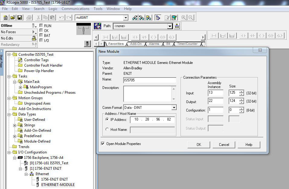
- From the Select Module Type dialog in the Catalog tab, select the Communication Module Type Category Filter, Allen-Bradley as the Module Type Vendor Filter, select ETHERNET-MODULE (Generic Ethernet Module) and press the Create button.
- In the New Module dialog, enter the following:
- The In-Sight vision system's name and IP address.
- The Connection Parameters:
- For In-Sight vision systems running In-Sight 5.x.x firmware, the Assembly Objects section defines the Assembly Instance that should be configured. For more information, see EtherNet/IP Object Model and Input/Output Assembly Objects.
For In-Sight vision systems running In-Sight 4.x.x firmware, the Assembly Objects section defines the Assembly Instance that should be configured. For more information, see EtherNet/IP Object Model and Input/Output Assembly Objects.
- After adding the vision system to the RSLogix project, the L5X rung import file can be used to create structured data for the connection.
Within the main program, right-click on an empty rung and select the Import Rungs... option.
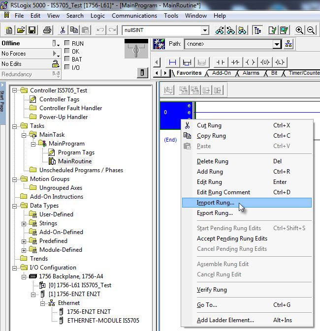
Navigate to the .L5X file and click the Import... button.
- If using In-Sight 4.10.x firmware, and RSLogix version 14-16, import the InSightGenEth_12_CopyRung.L5X file.
- If using In-Sight 4.10.x firmware, and RSLogix version 17-19, import the InSight_12_CopyRung.L5X file.
- If using In-Sight 5.x.x firmware, and RSLogix version 14-16, import the InSightGenEth_11_CopyRung.L5X file.
If using In-Sight 5.x.x firmware, and RSLogix version 17-19, import the InSight_11_CopyRung.L5X file.
The files are located in the following location: C:\Program Files (x86)\Cognex\In-Sight\In-Sight Explorer 5.x.x\Factory Protocol Description\RSLogix
Note: For information on which file to use, see Communicate with a Rockwell ControlLogix PLC.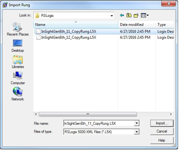
-
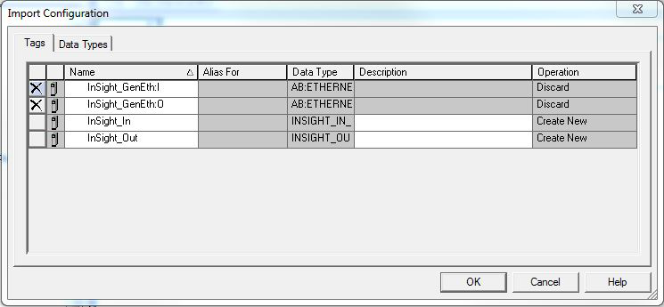
The Import Configuration dialog will then be used to change the names of the created tags to match the configuration.
-
The generic names of the Tags will need to be modified. The top two lines will have an X beside them, and the Name of each will need to be modified.
-
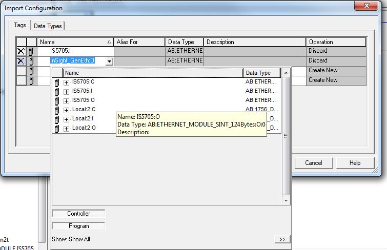
By clicking in the white space of the Name field, an arrow will appear, which will provide a drop-down menu that will contain replacement options for the default Name structure.
The list should contain names that match the name given in Step 4 (the name of the In-Sight vision system; in this example, the name given was IS5705, so the list contains IS5705:I and IS5705:O).
Replace the two generic names with the options in the drop-down menu.
-
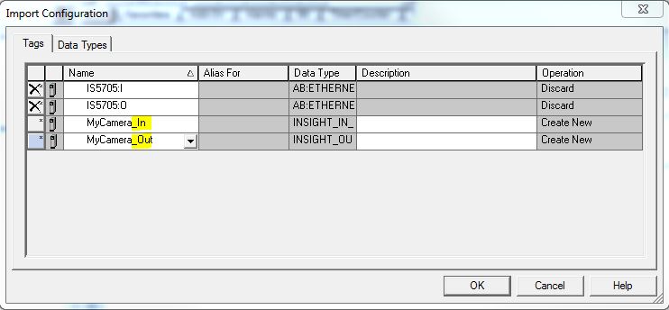
The bottom two lines will also need to be edited. Click on the text of the name so that the cursor icon appears and then replace the text prior to "_In" and _Out" with the name of the generic module or some other easily identifiable name (e.g. "MyCamera" in this example, since there is only one vision system).
 Note: he name given in this instance should be unique to each vision system that is added to the I/O configuration. If multiple vision systems are going to be deployed, these steps must be followed for each vision system, because each instance of the copy rungs that are created will point to a specific vision system. Therefore, for later troubleshooting, ensure that the names used are easily identifiable.
 - Once all of the Tags have been updated from their default values, press the OK button.
-
-
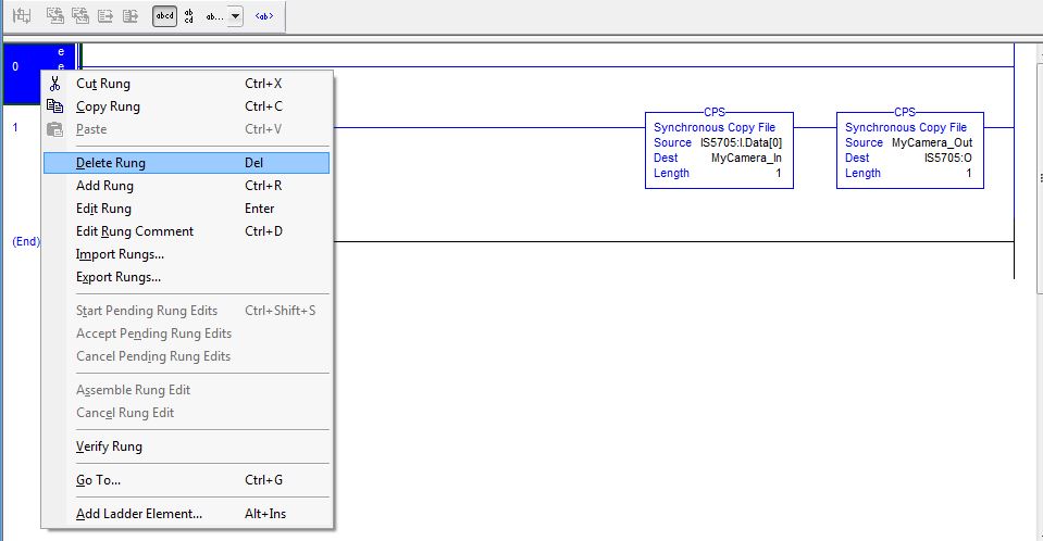
A new rung will have been added to the Main Routine below the rung that was added (the empty rung can be deleted).
- The project can now be downloaded to the PLC, and the PLC can be put into Run Mode.
-
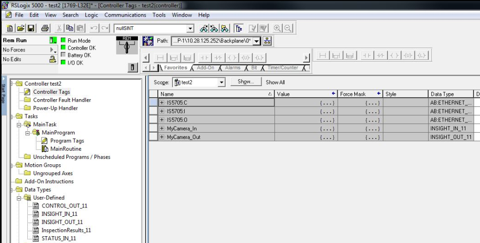
Once the rungs holding the copy instructions have been run, the new tags will be created in the Controller Tags table.
In this example, the IS5705:I and IS5705:O tags are the raw input and output assemblies from the vision system, and the MyCamera_In and MyCamera_Out will contain the Control and Status blocks, as well as the User Data and Inspection Result arrays.