 Communicating Over Modbus TCP
Your In-Sight sensor can act as a Modbus server to other networked Modbus TCP devices.
To configure your In-Sight sensor as a Modbus server:
- In the Communications group box, press the Add Device button.
-
From the Device Setup group box, select either PLC or Other from the Device drop-down list.
Note: If you select PLC, select either your PLC manufacturer or Other from the Manufacturer drop-down list to enable Modbus TCP Server as an option in the Protocol drop-down list. - Select Modbus TCP Server from the Protocol drop-down list.
- Press the OK button.
- By default, the Format Output Data tab appears first. The controls for both tabs are identical, and are enabled after data has been added.
-
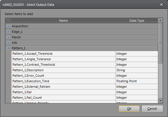
Press the Add button to launch the Select Input Data or Select Output Data dialogs (depending upon which tab is selected). The Select Input Data or Select Output Data dialogs contain the data from any Location or Inspection Tools that were added to your job and the overall job results (output only). From the dialog, select the data that you want to expose over Modbus, and press the OK button.
-
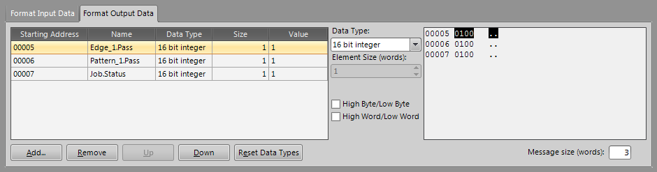
Once you have added your data, the data will appear in the table, displaying the name, data type, size, value and the starting register number of the selected data (this number is referenced by the Modbus client's Read and Write commands, and defines which signal is in which register). To the right of the table is a Modbus registers preview window, which displays how the data is formatted in to the Modbus registers.
-
You can customize the default data type by selecting a different data type from the Data Type drop-down list.
Note:- If you select String or Byte-Swapped String from the Data Type drop-down list, the Element Size (words) control will be enabled and you can specify the string length by choosing the correct number of words.
- The EasyBuilder implementation of the Modbus TCP protocol does not support bit, 8-bit or unsigned data types.
-
You can also customize the byte order of 32 bit floats and integers by specifying Low Byte first versus High Byte first by un-checking the High Byte/Low Byte checkbox (by default, it is unchecked). You can customize the word ordering of 32 bit floats and integers by specifying Low Word first versus High Word first by un-checking the High Word/Low Word checkbox (by default, it is unchecked). Any changes will be updated in the Modbus registers preview window.
Note: Any changes made to the byte or word ordering will affect all the data signals in the Format Output Data and Format Input Data tabs. - You can rearrange the order of the data that will be sent or received by selecting the data from the list and clicking either the Up or Down buttons to set the desired order.
- Once you have finished configuring your In-Sight vision system, you will need to configure your Modbus client to send the Read and Write commands, which will be sent to the In-Sight vision system to read/write data.