Communicate with a Siemens PLC on a PROFIBUS Network
An In-Sight vision system can communicate with devices on a PROFIBUS network using an Anybus X-gateway and TCP/IP Modbus protocol. This topic explains how to install and configure the gateway, how to configure the PLC programming software (Siemens Step 7), and how to set up In-Sight Explorer to communicate with a Siemens PLC on a PROFIBUS network.
The examples in this topic were written assuming that you are using the following components:
- Anybus X-gateway and HMS Anybus IPconfig software
- In-Sight vision system running firmware version 3.41.00 or higher
- Siemens S7-300 or S7-400 series PLC with PROFIBUS option
- Siemens Step 7 programming software
Install and Configure an Anybus X-gateway
The steps contained in this section explain how to install and configure the Ethernet portion of the Anybus X-gateway.
To install and configure an Anybus X-gateway:
- Download and install the HMS Software utility Anybus IPconfig. This utility uses the HMS IP Configuration Protocol (HICP), which provides a simple way to configure Anybus based Ethernet interfaces.
- Using a PC with Ethernet connectivity, run the Anybus IPconfig. A window will display all Anybus-based Ethernet interfaces, and their IP addresses, discovered on the network.
- Using the rotary PROFIBUS node address switches on the Anybus X-gateway, set the PROFIBUS node address. Please refer to the Anybus-X PROFIBUS Slave Network Interface Addendum for more information.
- Physically mount and connect the Anybus X-gateway hardware. Please refer to the Anybus X-gateway manual for more information.
- After the Anybus X-gateway hardware has been properly mounted and all cable connections have been made, provide power to the Anybus X-gateway hardware and wait 30 to 60 seconds for the device to power up. Once the Anybus-X Gateway hardware has power, the Ethernet LED status indicators should be either green or flashing green.
- From the Anybus IPconfig utility, click the Scan button to refresh the window that displays all Anybus-based Ethernet interfaces. The newly added Anybus X-gateway hardware should appear in the list, with a default IP address of 192.168.0.1.
- If the settings for the Anybus X-gateway need to be altered, double-click on the Anybus X-gateway in the list. This will display a dialog to assign IP addresses using DHCP or through a static IP address, subnet mask, default gateway and DNS server. Once the settings have been finalized, click on the Set button to continue.
- Finally, from the Anybus IPconfig utility, click the Scan button to refresh the window that displays all Anybus-based Ethernet interfaces. The Anybus X-gateway hardware should appear in the list, with the new IP address, if it was altered.
Connect an Anybus X-gateway to a Siemens PLC on a PROFIBUS Network
This section provides steps for connecting, and verifying, PROFIBUS communications between a Siemens PLC and an Anybus X-gateway.
The Anybus X-gateway exchanges data between a PROFIBUS network and a TCP/IP Modbus network; this allows for an In-Sight vision system's inputs and outputs to be sent to the processor's memory in the Siemens PLC. Once these values are established, they are synchronized at an interval defined by the update rate of the PROFIBUS network.
Set Up the PROFIBUS Communications with the Anybus X-gateway
To set up the PROFIBUS connection between a Siemens controller and an Anybus X-gateway, the Anybus X-gateway must first be added to the controller's hardware configuration, using the Siemen's HW Config tool:
-
Open the SIMATIC manager and load the PLC's project.
-
Select the SIMATIC 300 or SIMATIC 400 node and then double-click the Hardware node from the object list.

- The
Siemen's HW Config tool will now appear. In order to add PROFIBUS nodes
to the Controller, a PROFIBUS system must be present in the hardware configuration
diagram. If there is not a PROFIBUS:DP master system in the hardware configuration
diagram, follow these steps to add one:
- Under the Controller's slot in the rack configuration, find the DP or MPI/DP module, and then double-click on the module.
- From the Properties dialog, in the Operating Mode tab, ensure that the DP Master radio button is selected. In the General tab, ensure that the Interface type is set to PROFIBUS.
- If the device's addresses need to be changed, click on the Properties... button.
- From the listview, select the PROFIBUS subnet and click the Properties... button. If necessary, rename the network and change the Transmission Rate and Highest PROFIBUS Address.
- Click the OK button to accept any changes made to the dialogs.
A PROFIBUS:DP master system should now appear in the diagram.

- If
this is the first time that an Anybus X-gateway has been added to the
PROFIBUS network, the HMS Industrial Networks AB Anybus-X Gateway GSD
file must be installed. The latest version of this file can either be
downloaded from the HMS Website, or by contacting HMS directly. Perform
the following steps to install the Anybus-X Gateway GSD file:
- From the HW Config tool, select Options > Install GSD Files from the menu.
- Press the Browse button and select the GSD folder that contains the HMS_1013.GSD file.
- Press the Select All button, then click the Install button to install the hardware description for the Anybus X-gateway.
-
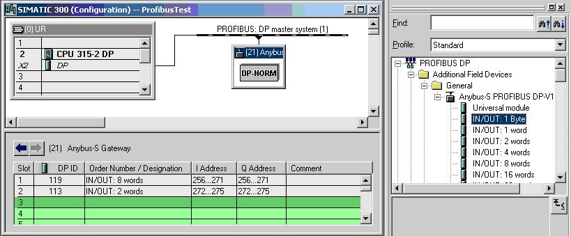
To add an Anybus X-gateway device to the PROFIBUS network, browse to the Anybus-S PROFIBUS DP-V1 node in the Hardware Catalog (it can be found in the PROFINET DP > Additional Field Devices > General node in the tree). Drag the instance of the Anybus-S PROFIBUS DP-V1 device on to the PROFIBUS DP master system in the hardware configuration.

- Set the PROFIBUS node address to the address of the Anybus X-gateway device that will be connected to (the Anybus X-gateway PROFIBUS node address is set using the rotary PROFIBUS node address switches on the Anybus X-gateway).
- The Anybus X-gateway device should now appear, at the specified address, in the PROFIBUS:DP master system.
-
To change the name of the device, double-click on the node in the configuration and change the "Designation" field to the new name.
-
Next, the Input/Output byte settings need to be set for PROFIBUS network. The Anybus X-gateway's default setting for input and outputs on each network is 20 bytes (10 words). To configure the PLC to access all 20 I/O bytes over the PROFIBUS network, first, expand the Anybus-S PROFIBUS DP-V1 node in the Hardware Catalog. From the Anybus-S PROFIBUS DP-V1 node, select the "IN/OUT:8 words" module and drag-and-drop the selected module onto the grid in Slot 1. Next, select the "IN/OUT:2 words" module and drag-and-drop it onto the grid in Slot 2. This will map 10 words in the PLC for use with the Anybus X-gateway.
Note: For more information on changing the default setting of the 20 I/O bytes, please see Chapter 5 of the Anybus-X Generic Gateway User Manual. - After the Anybus X-gateway has been added to the PROFIBUS system, using the HW Config Utility, the project can be saved and compiled, and then downloaded to the PLC.
- Once the project has been successfully downloaded to the PLC, on the Anybus X-gateway, the Gateway Status LED and PROFIBUS Online Status LED should both appear green, indicating successful communications with the PROFIBUS PLC.
Verify PROFIBUS Communications
Following the above steps, the Anybus X-gateway has now been added as an Input/Output device in a Siemens project. After the project is downloaded to the controller, cyclic data transfers will be initiated.
To verify a proper I/O connection between the PLC and Anybus X-gateway, perform the following steps:
- Set the Siemens controller's Operating Mode to Run.
-
Open the HW Config tool in Online mode. The Anybus X-gateway should be displayed, with no errors (an error is signified by a red line through the Anybus X-gateway's network icon); this will signify that the PROFIBUS connection has been completed correctly.

Connection Established

Connection Error
- Double-click the Anybus X-gateway box in the PROFIBUS(1): DP master sytem (1) network. In the General tab, the status should display either "OK" or "Module available and o.k."
-
In the HW Config Utility, with the Anybus X-gateway selected, right-click the IN/OUT:8 words module, and select Monitor/Modify from the menu.

- Check the Monitor checkbox from the Run conditionally subsection of the Monitor/Modify dialog. In the lower right-corner of the dialog, the word RUNNING should be displayed; in the Status value column, a status code should be returned for each of the PIW input word addresses listed in the Address column.
Connect an Anybus X-gateway To an In-Sight Vision System via TCP/IP Modbus
This section describes connecting an Anybus X-gateway to an In-Sight vision system, using TCP/IP Modbus communications. For more information, see Modbus TCP Communications.
- Please refer to the Open Modbus/TCP Specification (External link; requires Internet access. Published by Modicon.) and the InSightModbus.doc (available from the Cognex Support Website) for more information.
- The following samples assume that the default Modbus/TCP Modbus Address Mode setting in the Anybus X-gateway is Enabled, which is the default setting. If the setting is changed to Modbus Address Mode Disabled, then the Read Holding Registers and Write Multiple Registers QueryDevice functions in the ProfibusGateway.cxd need to be updated to reflect the new register address of 1024 address instead of 0. Refer to the X-Gateway Interface Addendum Ethernet Slave Interface, Chapter 5 pages 5-1 through 5-4.
Set Up TCP/IP Modbus Communications In In-Sight Explorer
TCP/IP Modbus client functionality is enabled on In-Sight vision systems, but this server functionality is not needed in this model, because the Anybus X-gateway acts as the TCP/IP Modbus server (slave).
- In In-Sight Explorer, select the In-Sight vision system or emulator that is to be configured from the In-Sight Network pane.
- From the File menu, select New Job to load a new job on to a vision system or emulator.
- From the Palette, select the Snippets tab and expand the Communications folder. Load the ProfibusGateway.cxd file to cell A2 in the In-Sight Explorer spreadsheet by either first selecting A2 and double-clicking on the ProfibusGateway.cxd or drag-and-drop the file into cell A2.
- Save the new job to the vision system or emulator as ProfibusGateway.job.
- Double-click cell A5 and enter the IP Address of the Anybus X-gateway (if necessary, run the HMS Anybus IPconfig software utility to return the Anybus X-gateway's IP address).
- TCP/IP Modbus communications require that an In-Sight client (master) has the following functions present in the job: TCPDevice and QueryDevice. The TCPDevice function is used to create the network connection between the remote device, in this case, the Anybus X-gateway, and an In-Sight vision system. The QueryDevice function is used to construct the Modbus Function Code command of the TCP/IP Modbus packet. The ProfibusGateway.cxd file contains a TCPDevice function in cell C5, and two QueryDevice functions: one in cell B15 for Read requests, and the other in cell B27, for Write requests. For more information about TCPDevice, see TCPDevice and for more information about QueryDevice, see QueryDevice.
-
The Anybus X-gateway supports the following Modbus Function Codes in the QueryDevice function:
Function Code Function Name 3
Read multiple registers
4
Read input registers
6
Write single register
7
Read exception status
8
Diagnostics
16
Force multiple registers
22
Mask write register
23
Read/Write registers
-
Double-click the QueryDevice function, located in cell B15, and ensure that it has the following parameter settings:

Parameter Input Number Parameter Input Name Parameter Input Value Description 1
Event
$A$15
A cell reference to an Event button.
2
Device
$C$5
A cell reference to the TCPDevice function in cell C5.
3
Data
0
Modbus header, Transaction Identifier, upper byte = 0.
4
Data
0
Modbus header, Transaction Identifier, lower byte = 0.
5
Data
0
Modbus header, Protocol Identifier, upper byte = 0.
6
Data
0
Modbus header, Protocol Identifier, lower byte = 0.
7
Data
0
Field Length, upper byte = 0.
8
Data
6
Field Length, lower byte = 6 (bytes to follow).
9
Data
0
Unit ID, byte not used = 0.
10
Data
$C$12+3
Modbus Function Code byte; in this example, this input will equal 3 or 4.
Note: When the Modbus Function Code byte is set to 3, In-Sight reads the holding registers (the data written via TCP/IP Modbus); when the Modbus Function Code byte is set to 4, In-Sight reads the input registers (data written via PROFIBUS).11
Data
0
Modbus reference address, upper byte = 0.
Note: Input registers may be read using Read multiple registers (Function Code 3) from address 1024, or using Read input registers (Function Code 4) from address 0.12
Data
0
Modbus reference address, lower byte = 0.
Note: Input registers may be read using Read multiple registers (Function Code 3) from address 1024, or using Read input registers (Function Code 4) from address 0.13
Data
0
Word (register) count, upper byte = 0.
14
Data
$B$8
Word (register) count, lower byte; in this example, this input will equal 1, 2, 3, 5 or 8.
-
The TCP/IP Modbus response packet from the Anybus X-gateway is stored in the binary structure of the QueryDevice function; these return values are read in In-Sight Explorer by the BGetInt function. This function returns integer values from a specific byte from a binary structure, and the response is formatted as follows:
Byte Number Modbus Response Description Byte 7
Modbus Function Code
In this example, 3 or 4. If the command fails, 128 is added to the Function Code (the value returned would then be 131 or 132, see cell E15).
Byte 8
Byte Count
In this example, 2 registers (words) = 4 bytes. See cell E15.
Byte 9/10
Value in Register 0
These values are in the two-byte format. In the ProfibusGateway.cxd file, the BGetInt function in cell D18 reads the binary value at Byte 9 (the lower byte of the word read).
Byte 11/12
Value in Register 1
These values are in the two-byte format. In the ProfibusGateway.cxd file, the BGetInt function in cell D19 reads the binary value at Byte 11 (the lower byte of the word read).
Byte 13/14
Value in Register 2
These values are in the two-byte format. In the ProfibusGateway.cxd file, the BGetInt function in cell D20 reads the binary value at Byte 13 (the lower byte of the word read).
Byte 15/16/17/18
Value in Registers 3 and 4 that store a floating-point number
These values are in the floating-point format. In the ProfibusGateway.cxd file, the BGetInt function in cell D21 reads the binary value at Byte 15 (the lower byte of the word read).
Byte 19/20/21/22/23/24
Value in Registers 5, 6 and 7 that store a string (in byte array)
These values are in the string format. In the ProfibusGateway.cxd file, the BGetInt function in cell D22 reads the binary value at Byte 19 (the lower byte of the word read).
- The QueryDevice function, in cell B27, for the Write request, is formatted in the same manner as the Request and Response packets.
Read Data to an In-Sight Vision System from a PLC Via PROFIBUS
Following the example provided by this model, the Input Buffer of the Anybus X-gateway is the data source being read; this buffer holds the data requested by the In-Sight vision system (on the TCP/IP Modbus network) from the PLC (on the PROFIBUS network).
- Continue using the In-Sight Explorer job created in the Setting Up TCP/IP Modbus Communications in In-Sight Explorer section.
- Open the SIMATIC manager and load the PLC's project. If necessary, download the project to the Siemens controller and set the Operating Mode to Run.
- In the SIMATIC manager, create a new Variable Table by right-clicking on the PLC and selecting Insert New Object from the Variable Table menu. Name and then open the new table.
-
Add five items to the table, as in the table below.
Offset Address Display Format 0
PQW 385
DEC
+2
PQW 387
DEC
+4
PQW 389
DEC
+6
PQD 391
FLOATING_POINT
+10
PQD 395
CHARACTER
+14
PQD 399
CHARACTER
Note: The addresses are predicated on the "IN/OUT:8 words" module being at the Output Address of PQW 385. If the "IN/OUT:8 words" module is using a different Output Address, apply the specified offset to the Output Address to return the correct Output Address. - In the SIMATIC Manager, open Configured CPU from the PLC > Connect To menu. The system will now be Online and monitoring the addresses entered in the Variable Table.
-
Enter values for the five items added to the Variable Table, and then select Activate Modify Values from the Variable menu.

- Set the vision system Online.
- In cell A8 of the ProfibusGateway.cxd file, select 8 for the number of registers (16 bytes).
-
In cell C12, select Input Registers from the drop-down list for the Read Registers.

- Click on the Read Button in cell A15 to update the results. The values in cells D18-D22 should change to reflect the values that were entered in the Variable Table.
Write Data From an In-Sight Vision System To a PLC Via PROFIBUS
Following the example provided by this model, the Output Buffer of the Anybus X-gateway is the data source being written to; this buffer holds the data written by the In-Sight vision system (on the TCP/IP Modbus network) to the PLC (on the PROFIBUS network).
- In cell A8 of the ProfibusGateway.cxd file, select 8 for the number of registers (16 bytes).
- In cell C12, select Holding Registers from the drop-down list for the Read Registers; this will read data from the same registers that are being written from within the In-Sight job.
- Next,
adjust the values in cells D30-D34 so that they are valid data types for
the application. Enter values into the EditInt
cells for:
- The three integers in cells D30-D32. The minimum value is -32768 and the maximum is 32767, so the value must be a valid integer between that range.
- The floating-point value in cell D33. The minimum value is ±1.175495e-38 and the maximum value is ±3.402823e+38, so the value must be a valid floating-point value between that range.
The 6 byte string in cell D34. The string can be no longer than 6 characters/bytes.

-
Click the Write Button in cell A27 to write the results from the In-Sight Explorer spreadsheet to the PLC.

- Click the Read Button in cell A15. Yhe values in cells D18-D22 should change to reflect the values that were entered in cells D30-34.
- Open the SIMATIC manager and load the PLC's project. If necessary, download the project to the Siemens controller and set the Operating Mode to Run.
- In the SIMATIC manager, create a new Variable Table by right-clicking on the PLC and selecting Insert New Object from the Variable Table menu. Name and then open the new table.
-
Add five items to the table, as in the table below.
Offset Address Display Format 0
PIW 325
DEC
+2
PIW 327
DEC
+4
PIW 329
DEC
+6
PID 331
FLOATING_POINT
+10
PID 335
CHARACTER
+14
PIW 339
CHARACTER
Note: The addresses are predicated on the "IN/OUT:8 words" module being at the Input Address of PIW 325. If the "IN/OUT:8 words" module is using a different Input Address, apply the specified offset to the Input Address to return the correct Input Address. -
In the SIMATIC Manager, open Configured CPU from the PLC > Connect To menu. The system will now be Online and monitoring the addresses entered in the Variable Table. The values in the Variable Table should change to reflect the values that were entered in the In-Sight Explorer spreadsheet.
 Note: A Siemens S7 PLC can read out one, two or four bytes consistent from the I/O-image directly by accessing the data as a Byte, a Word or a DoubleWord. However, if you want to read out more than 4 bytes in a data string, it is necessary to use the System Function Blocks SFC14 and SFC15. For more information refer to Section 5.2.2 of the HMS document How to Configure an Anybus PROFIBUS Slave Module with a Siemens Step7 PLC available on the support page of the Anybus website (Anybus-X gateway).