Communicate with a Mitsubishi Automation Controller on CC-Link IE Field Network Basic
CC-Link IE Field Basic is a protocol designed to integrate Ethernet devices into a Mitsubishi Automation Controller. As opposed to the existing SLMP (MC Protocol), the Mitsubishi automation controllers act as the master, driving the communications to the slave devices over standard UDP messaging. The communications support 64 bits and 32 16-bit words of data per station in each direction, with each slave supporting 4 stations. The data is mapped into controller memory through the Mitsubishi setup tools (GXWorks 2/3).
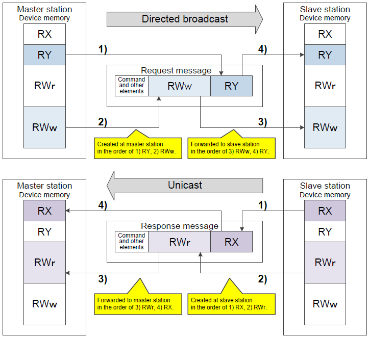
Once the protocol is enabled and the vision system is configured in the controller, the controller will begin cyclic communications to the In-Sight vision system through a request/response mechanism.
Configure In-Sight Vision Systems for CC-Link Protocol Communications
This section describes how to connect to an In-Sight vision system using CC-Link communications to a Mitsubishi Q-Series Automation Controller.
Enable CC-Link IE Field Basic
- To enable CC-Link IE Filed Basic from the EasyBuilder View, refer to the EasyBuilder Help (Communication > Device Setup > Communicating with Mitsubishi Devices > CC-Link IE Field Basic).
- For more information on CC-Link IE Field Basic, refer to Mitsubishi's CC-Link IE Field Network Basic Reference Manual.
In-Sight Explorer
- Open In-Sight Explorer and connect to the desired In-Sight vision system.
- From the Sensor menu, open the Network Settings dialog.
- In the Industrial Ethernet Protocols section of the dialog, select CC-Link IE Field Basic.
- Restart the In-Sight vision system, and the CC Link IE Field Basic protocol will be enabled upon completion of the power cycle.
Mitsubishi GX Works 2
- Open the Mitsubishi GX Works 2 software to connect their PLC to the In-Sight vision system.
- Click on the Built-in Ethernet Port Setting tab and presses the CC-Link IEF Basic Setting button.
- Check the Use the CC-Link IEF Basic checkbox.
- Click on the Network Configuration Setting button to open the CC-Link IEF Basic Configuration dialog.
- Add the vision system to the link scan list, and selects the desired number of stations (1-16) to scan on the vision system.
- Accept changes to the dialog.
- Select the PLC memory used to store the synchronized CC-Link IEF Basic registers.
- Accept all parameter dialogs and downloads the project to the PLC.
- After restarting the PLC, it will begin scanning the vision system over CC-Link IEF Basic.
Configure the In-Sight Vision System to Receive Image Acquisition Triggers
- Open the AcquireImage function's property sheet.
- Set the Trigger parameter to Industrial Ethernet.
- Place the In-Sight vision system Online. For more information, see Online/Offline.
- An In-Sight vision system can be triggered by directly manipulating the Trigger Enable and Trigger bits in the RY Block, or by monitoring the Trigger Ready, Trigger Ack and Missed Acq bits in the RX Bit Block.
Get Data From an In-Sight Vision System
- Right-click an empty cell and select Insert Function to open the Insert Function dialog. From the left pane, click on the Input/Output category, then double-click the FormatOutputBuffer function, from the right pane, to insert it into the spreadsheet.
- From the FormatOutputBuffer dialog, click on the Add button. This will initiate the cell selection mode; select the data that will be transferred to the MELSEC Automation Controller.
- If there is additional data to be sent, again, from the FormatOutputBuffer dialog, click on the Add button. Once again this will initiate the cell selection mode; select the additional data to transfer.
- Close the FormatOutputBuffer dialog by clicking the OK button.
- Right-click an empty cell and select Insert Function to open the Insert Function dialog. From the left pane, click on the Input/Output category, then double-click the WriteResultsBuffer function, from the right pane, to insert it into the spreadsheet. For more information, see WriteResultsBuffer.
- Set the WriteResultsBuffer function's Protocol Parameter to 8 = CC-Link IE Field Basic Bit or 9 = CC-Link IE Field Basic Word, and the Buffer parameter as a cell reference to the recently created FormatOutputBuffer function's Buffer data structure. For more information, see Cell References - Relative/Absolute.
- Optionally, set the Result Code parameter as a cell reference to a cell in the spreadsheet to retrieve the result code with the inspection results.
Send Data to an In-Sight Vision System
- Right-click an empty cell and select Insert Function to open the Insert Function dialog. From the left pane, click on the Input/Output category, then double-click the FormatInputBuffer function, from the right pane, to insert it into the spreadsheet.
- From the FormatInputBuffer dialog, click on the Add button and add a 32-bit float and a 32-bit integer to the list.
- Close the FormatInputBuffer dialog by clicking the OK button.
- Right-click
an empty cell and select Insert Function to open the Insert Function dialog. From the left pane, click on the Input/Output
category, then double-click the ReadUserDataBuffer
function, from the right pane, to insert it into the spreadsheet
.
- Set the ReadUserDataBuffer function's Buffer parameter as a cell reference to the recently created FormatInputBuffer function's Buffer data structure.
- Set the ReadUserDataBuffer function's Protocol parameter to 8 = CC-Link IE Field Basic Bit or 9 = CC-Link IE Field Basic Word.
- Once the functions have been implemented, place the In-Sight vision system Online to test the configuration.