Communicate with a Rockwell SLC 5/05 PLC
This section outlines a PCCC (PC3) Communications configuration between an In-Sight vision system and the PLC. This example uses the Allen-Bradley SLC5/05 and Rockwell 500 software.
Necessary Components
- In-Sight vision system with firmware version 2.2 through 4.9.1
- Rockwell RSLogix 500 programming software (version 4.5 or higher)
- Allen-Bradley SLC5/05 controller, with corresponding firmware to support RSLogix500
Using RSLogix 500
-
From within the RSLogix 500 software program, open the .RSS file, then open the Channel Configuration dialog (Project Folder > Controller Folder > Channel Configuration).
.gif)
- The Allen-Bradley SLC has 2 channels available for configuration: Channel 1 (Ethernet); and Channel 0 (DF1 Full Duplex - serial). Click on the Chan. 1 - System tab.
-
Configure Channel 1 (Ethernet) as necessary. Consult with a network administrator for proper settings.
Note: Verify that the IP/Subnet/Gateway parameters are correct on the PLC and the In-Sight vision system..gif)
-
Configure the Timeouts as required.
Message (MSG) Instruction
Message instructions may now be constructed within the application. Refer to the RSLogix 500 documentation for expanded instructions for developing messages. The following setup parameters can be configured within a Message (MSG) Instruction.
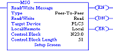
- Type: Peer-To-Peer. This cannot be modified.
- Read/Write: Select the function you want to perform on an In-Sight vision system. Read retrieves data from the In-Sight; Write sends data to the In-Sight.
- Target Device: Choose PLC5 to talk to an In-Sight vision system. This tells the SLC which communication protocol to use. The In-Sight vision system acts much like a ControlLogix controller (see Rockwell document 13862).
- Local/Remote: Choose Local to indicate that the In-Sight vision system is on the same network as the SLC; Remote tells the SLC that you will be communicating to an In-Sight on another network. For remote communication, you must direct the message through another device acting as a gateway to that secondary network. Typically, this could be an Allen-Bradley ControlLogix controller. (Refer to Rockwell documentation on how to address devices on other networks through a gateway.)
- Control Block: This is a temporary integer file that the MSG instruction uses to store data (i.e., IP address, message type, etc.). This is typically not the user data to be sent.
- Control Block Length: This is automatically computed by the MSG instruction.
- Setup Screen: Selecting Setup Screen will open the Message Instruction Setup dialog.
Setup Screen for the MSG Instruction
The following setup parameters can be configured within a MSG Instruction Setup screen.
General Tab
This Controller section:
- Communication Command: Should be the same command (READ/WRITE) that was chosen on the first screen (as seen in MSG Instruction screen). For more information, see Message (MSG) Instruction.
-
Data Table Address: This is the location of the data file on the SLC where data will be written to (READ) or sent from (WRITE) (as seen in MSG Instruction screen). In this instance, 'F8:0', 'F' indicates the float file, '8' indicates the file number 8, and '0' indicates the offset into that file (in this case, start at the 0th element). The figure below shows an example of the Float Table accessed from the RSLogix 500 main screen.
- Size in Elements: This is the number of elements (or individual data) to send. In this example, two elements are being sent (3.14 and 78.87).
- Channel: Depends on the configuration of the SLC. In the SLC, Channel 1 is the Ethernet port.
Target Device section:
- Message Timeout: Choose an appropriate length of time in which the In-Sight vision system will be able to respond. If the In-Sight does not respond within this length of time, the MSG instruction will error out. This parameter cannot be changed from this screen. Message Timeout is determined by the parameters entered in the Channel 1 setup dialog (refer to step 4 of Using RSLogix 500).
-
Data Table Address: This is the location on the In-Sight vision system where data will be read or written to. In this instance, 'F8:1', 'F' indicates that the data is of type float (real); '8' indicates that the In-Sight will ignore ? (data is always being written to the Input Assembly, and read from the Output Assembly); and the '1' has different meanings, based on whether or not a READ or WRITE is being performed.
When a WRITE is occurring, the '1' indicates the actual data byte offset into the data portion of the Input Assembly. When a READ is occurring, the '1' indicates the element. For example: If the message were a READ, 'F8:2' would instruct to read the 3rd element (the ':2' indicates the 3rd element, due to the SLC's 0-based index), which is of type Float from the Output Assembly (because a READ gets data from the In-Sight's Output Assembly). If the message were a WRITE, 'F8:12' would indicate to write a float value to the 12th byte of the data section of the Input Assembly. WRITE indicates the actual byte of the assembly to begin writing data in to; READ indicates an actual data element.
Note: The ST10:0 destination address is used for sending Native Mode commands to an In-Sight vision system. To send a string or other data type to an In-Sight, use a destination address other than ST10:0. - Local/Remote: Set to Local or Remote, depending on the application.
- MultiHop: This setting is dependent on the information previously entered. For successful In-Sight communication, this should YES at this time.
MultiHop Tab
The MultiHop tab is used to identify the address of the In-Sight system and the controller location. Both must be identified in order to route communications to the In-Sight vision system. As previously discussed, the In-Sight vision system acts as a ControlLogix module during PC3 communications.
Using the MSG Instruction to Receive Data
A MapSpec specifies a data mapping, which consists of a list of specifiers delimited by colon (:) characters. Each specifier has two parts: the starting byte and a data type code. The various data type codes are listed in the following table:
| Code | Data Type |
| i | 8-bit integer |
| u | 8-bit unsigned integer |
| il | 16-bit integer |
| ul | 16-bit unsigned integer |
| d | 32-bit unsigned integer |
| f | 32-bit floating-point number |
| s | text string |
In the following examples, assume that the In-Sight spreadsheet has a cell containing a WriteEIP function with a MapSpec of: '0f:4f:8il:10il:12il'
|
EXAMPLE: |
In the RSLogix500 MSG Instruction, we have 'N8: 2' for the target device data table address (DTA = 'N8:2'), and we are requesting 3 elements (n = 3). In the MSG instruction: 'N' indicates that integers are going to be transferred; '2' indicates that it will begin with the 3rd item of the MapSpec. |
The In-Sight vision system replies with the data at the 3rd item in the MapSpec (8il), followed by 10il and 12il (3 elements, all integers).
|
EXAMPLE: |
DTA = 'F8: 1' n = 2 The reply would be the data at 4f (the 2nd item of the MapSpec) and In-Sight attempts to combine all the data at 8il and 10il to make the second float. Only contiguous like elements (e.g. 2 float, 42 integers, 13 characters, etc.) can be requested. |
|
EXAMPLE: |
DTA = 'F8: 0' n = 2 The reply would be the data at 0f and 4f (2 elements, both floats). |
|
EXAMPLE: |
DTA = 'N8: 3' n = 2 The reply would be the data at 10il and 12il (2 elements, both integers). This example reinforces getting contiguous elements of the same type. |
Sending Native Mode Commands from an SLC5/05
- Configure the SLC5/05 as necessary.
-
Create a String Table that will hold your Native Mode commands. For more information, see Native Mode Commands.
-
Add the required Native Mode command strings to the Data File.
-
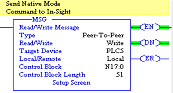
Add a new Message (MSG) instruction to your ladder logic and configure it as shown in the following example:
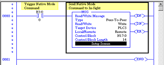
-
Enter the MSG Setup Screen and configure it as follows:
THIS CONTROLLER (SLC) PARAMETER DESCRIPTION Data Table Address:
ST10:1
1st element from String Table (ST) created above
Size in Elements:
1
Always set to 1. PCCC MSG only allows for 1 string (therefore 1 command) to be sent at a time.
Channel:
1
Set this to the Ethernet Channel of your controller.
TARGET DEVICE (IN-SIGHT SENSOR) PARAMETER DESCRIPTION Message Timeout:
(From the Channel Configuration dialog)
Data Table Address:
ST10:0
This is the destination address. For Native Mode commands, this will always be ST10:0. For more information, see Native Mode Commands.
-
Click the MultiHop tab and configure it as required:
EXAMPLE: In this example, only the IP address of the destination In-Sight vision system needed to be set:
- When everything is configured, close the MSG window.
- Save your ladder logic, download it to the controller, then go online and set the controller in RUN mode.
- Trigger the message to send it to the In-Sight vision system.
Message Instruction Results
The Enable (EN) bit of the message instruction will be set to 1 when the input to the instruction is set high. The Done (DN) bit will be set to 1 when In-Sight has replied that the Native Mode command was received and executed with success. If the Error bit (ER) is enabled (set to 1), there has been a problem with the message instruction. If an error occurs, click the Setup Screen for the MSG instruction. For more information, see Native Mode Commands.
The Error Code will be shown at the bottom of the window. Error codes
are listed in the table below:
Error Codes
ERROR CODE | DESCRIPTION | NATIVE MODE RETURN CODE |
|---|---|---|
00 | Success - No Error | 1 |
10 | Illegal command or format | 0 |
EE | Command cannot be executed | -2, -4 or -5 |
D9 | Reply not received before user-specified timeout | NA |
F2 | Invalid parameter or invalid data | -1 |