Establish the Connection Using the Add-On Profile
This topic covers how to establish an implicit messaging connection with a single ControlLogix PLC using the Add-On Profile (AOP) for an In-Sight vision system running 4.x.x firmware.
-
Open RSLogix 5000 and load the PLC's project.
Note: The PLC must be Offline to add connections in RSLogix 5000. -
Under the I/O Configuration node, select the Ethernet Node under the Ethernet Module, right-click on the icon and select New Module from the menu:
-
When the following dialog appears, select your model of In-Sight Vision System from the list. This option will appear once the Add-On Profile (AOP) is installed.
-
After the selection is made, the configuration dialog for the In-Sight Vision system will be displayed:
Note: The Time Sync tab is displayed only when connected to an In-Sight 5000 series vision system. For more information, see Time Sync Tab- In-Sight 4.x.x Firmware.
The following fields need to be configured:
- Name: This is the name given to the generic EtherNet/IP device; the tags created in RSLogix 5000 will be based on this name. It is recommended that the In-Sight vision system's name be used, to maintain consistency.
- IP Address: The IP address of the In-Sight vision system.
- Host Name: This setting is optional; only use this setting if there is a Domain Name Server (DNS) on the network.
- The Change button can be used to set the amount and type of data to be transferred between the In-Sight Vision System and the PLC. Electronic Keying can also be enabled using this button.
-
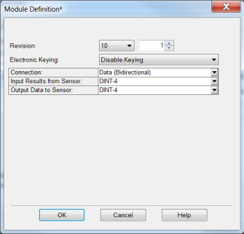
(Optionally) The electronic keying can be disabled using the Change button if necessary.
To disable keying: In the Module Definition dialog, select Revision 10 and select Disable Keying. Then click OK.
-
After accepting the general communication parameters, the next step in the configuration process is displayed in the figure below:
The following fields can be configured:
-
Requested Packet Interval (RPI): This field specifies the Requested Packet Interval (RPI), which defines the amount of time (in milliseconds) between data exchanges across an implicit messaging connection.
Note: Beginning in In-Sight firmware version 3.30.00, the RPI value no longer has to be longer than the job execution time; implicit messaging connections now run asynchronous to the job execution. However, small RPI times (<20ms) may negatively impact the performance of vision jobs. For best results, the RPI time should be set to no more than half the time between when the In-Sight vision system completes the job execution and when the PLC requires the data. - Major Fault On Controller If Connection Fails While in Run Mode: This option will cause the controller to generate a major fault when the connection fails.
-
Inhibit Module: Checking this box prevents the PLC from attempting to establish a connection with an In-Sight vision system.
Note: If the In-Sight vision system appears to be stuck in "Standby" mode, then inhibiting and re-enabling the module can cause the module to become operational again.
-
-
After adding the module to ControlLogix, the I/O tree should appear as follows:
- RSLogix
5000 will then create tags that map to the In-Sight vision system's Input and
Output Data, based on the name given to the device.
InSight_Top:I Scheduled Input: The table below represents the data that is sent FROM the In-Sight vision system to the PLC:
InSight_Top:O Scheduled Output: The table below represents the data sent TO the In-Sight vision system from the EtherNet/IP client (ControlLogix):