Transferring Data With an In-Sight Vision System via PROFINET - In-Sight 4.x.x Firmware
This topic covers the transfer of data to and from an In-Sight vision system running In-Sight 4.x.x firmware, and a Siemens PLC.
Enabling PROFINET Communications on an In-Sight Vision System
Before PROFINET communications can be established with an In-Sight vision system, the vision system must be configured to enable PROFINET, using the Network Settings of the In-Sight vision system.
- Open In-Sight Explorer and connect to an In-Sight vision system.
- From the Sensor menu, open the Network Settings dialog.
-
In the Protocol Services section of the dialog, select PROFINET and press the Settings button to enable and configure the vision system's Station Name, as seen by the Siemens PLC, using the PROFINET Settings dialog.
Note: If the Station Name is not set, the PLC will see the host name, which may not be identical to the vision system's host name, because the PROFINET protocol will translate characters it does not support to characters it does support. - Back in the Network Settings dialog, press OK.
- Restart the In-Sight vision system, and the PROFINET service will be enabled upon completion of the power cycle.
Setting Up the Connection
To set up a PROFINET I/O connection between an In-Sight vision system and a Siemens controller, the In-Sight vision system must first be added to the controller's hardware configuration, using the Siemen's HW Config tool:
- Open the SIMATIC manager and load the PLC's project.
-
Select the SIMATIC 300 or SIMATIC 400 node, then double-click on the Hardware node in the object list.

-
The HW Config tool will now appear. In order to add PROFINET IO nodes to the controller, a PROFINET IO system must be present in the hardware configuration diagram; if there isn't a PROFINET IO system in the diagram, complete the following steps:
- Ensure that the PROFINET IO interface on the CPU has been assigned a subnet address; to verify this, double-click on the PROFINET IO module on the CPU. If the PROFINET IO module's Networked status indicates "No," then click the Properties button and add a new subnet.
- Once the PROFINET IO interface on the CPU has been assigned a subnet, add a PROFINET IO system to the hardware configuration diagram by right-clicking the PROFINET IO module in the PLC configuration and selecting Insert PROFINET IO System.
-
If this is the first In-Sight vision system to be added to the PROFINET network, the In-Sight GSD file (version 2.3, provided by Cognex) will need to be installed. To install the In-Sight GSD file, follow these steps:
- From the HW Config tool, select Options > Install GSD Files from the menu.
- Press the Browse button and select the GSD folder from this location: C:\Program Files (x86)\Cognex\In-Sight\In-Sight Explorer x.x.x\Factory Protocol Description\GSD.
- Press the Select All button, then click the Install button to install the hardware description for the In-Sight vision systems.
Note:The In-Sight Explorer software contains below GSD files. Please use the appropriate GSD file based on your vision system model and its firmware version.
Firmware Version and In-Sight model GSD file Description 5.8.0 or later, except In-Sight 5705/5705C vision systems* V2.34 (GSDML-V2.34-Cognex-InSightClassB-xxxxxx.xml) Supports Conformance Class B (newer PROFINET stack). The Class B configs are suffixed with CC-B, indicating that the config is Class B (for example, In-Sight IS2XXX CC-B). 5.7.x or earlier and In-Sight 5705/5705C vision systems V2.3 (GSDML-V2.3-Cognex-InSight-xxxxxxx.xml) Uses the original Conformance Class A PROFINET stack. *The In-Sight 5705 and 5705C vision systems do not support Conformance Class B and V2.34 GSD.
To add an In-Sight vision system to a PROFINET network, browse to the In-Sight node of the Hardware Catalog (PROFINET IO > Additional Field Devices > Sensors > Cognex Vision Sensors), and then drag an instance of the In-Sight vision system into the PROFINET IO System in the hardware configuration.
-
Set the device name to the exact name of the In-Sight vision system being connected to.
Note: If an underscore was used in the In-Sight vision system's name, the underscore will have to be replaced by a hyphen when the vision system's name is input in PROFINET. For example, if the camera was named "Camera_Top" in In-Sight Explorer, it will need to be renamed to "Camera-Top" in PROFINET. -
The In-Sight vision system should now be displayed as a device on the PROFINET IO system, along with the In-Sight vision system's various modules supported by the particular PROFINET IO implementation.
 Note:
Note:Once the In-Sight vision system has been added as a device on the PROFINET IO system, to prevent the PLC from assigning the vision system a new IP address, disable the Assign IP address via IO controller checkbox in the vision system's Properties dialog. To open the Properties dialog and disable the checkbox (which is checked by default), either double-click the vision system device or right-click it and select Object Properties.
 If using Siemens Step 7 software to configure your PLC, click here.
Tip: The Siemens Step 7 software will assign default I/O addresses to each of the modules added for the In-Sight vision system based on the definitions of each module in the In-Sight GSD file (see the above figure). It is allowed to change any or all of these I/O addresses. All of the modules that map out discrete bit data (acquisition control and status, inspection control and status, and soft event control) must be assigned addresses that are within the process-image input and output memory areas of the PLC. Most newer firmware on Siemens S7 series PLCs allow the sizes of this memory area to be changed (default size is 256 bytes, I0.0 - I255.7, Q0.0 - Q255.7). Other older firmware or models that are not configurable (consult Siemens PLC documentation) have a fixed size, usually 256 bytes. This can be seen in the picture above where each of the discrete bit data modules are mapped into I/O addresses starting at 0 and the byte/word modules are assigned addresses starting just above the process-image input and output memory areas of the PLC (256 and higher).
If using Siemens Step 7 software to configure your PLC, click here.
Tip: The Siemens Step 7 software will assign default I/O addresses to each of the modules added for the In-Sight vision system based on the definitions of each module in the In-Sight GSD file (see the above figure). It is allowed to change any or all of these I/O addresses. All of the modules that map out discrete bit data (acquisition control and status, inspection control and status, and soft event control) must be assigned addresses that are within the process-image input and output memory areas of the PLC. Most newer firmware on Siemens S7 series PLCs allow the sizes of this memory area to be changed (default size is 256 bytes, I0.0 - I255.7, Q0.0 - Q255.7). Other older firmware or models that are not configurable (consult Siemens PLC documentation) have a fixed size, usually 256 bytes. This can be seen in the picture above where each of the discrete bit data modules are mapped into I/O addresses starting at 0 and the byte/word modules are assigned addresses starting just above the process-image input and output memory areas of the PLC (256 and higher).
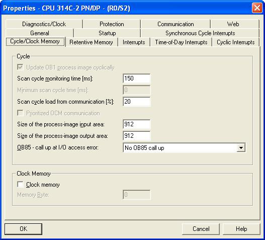
A typical use case would be a configuration as shown in the figures below, which keeps each In-Sight vision systems' I/O addresses in a more contiguous block than what the Step 7 software assigns. In order for the PLC logic to access the new I/O bit addresses, open the HW configurator in Step 7 software, open the properties of the PLC (CPU), go to the Cycle/Clock Memory tab of the dialog and the Size of the process-image input area and Size of the process-image output area. In the example the sizes of the input and output areas should be changed to 912 to so that the discrete bit data for the In-Sight vision system is accessible using the PLC's I and Q addresses for the vision system. If these process-image sizes are not changed, the bit values will not be read or written to correctly, although byte/word values will update correctly. Refer to the Siemens PLC documentation for the additional memory overhead required when these process image sizes are changed.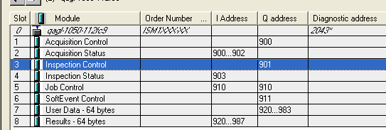
All of the available modules for the In-Sight vision system are automatically added to the hardware configuration. These modules allow access to the various subsystems in the In-Sight vision system. The default User Data and Inspection Results modules are 64 bytes in size. In order to change the sizes of the modules, delete them from the list and drag the appropriately sized module from under the In-Sight Data Modules folder in the Catalog tree to the Slot in the list.
-
Once the In-Sight vision system has been added to the PROFINET system in the HW Config utility, the cyclic transfer rate can be adjusted by opening the properties window of the PROFINET IO System. This can be done by double-clicking on the PROFINET IO System in the hardware configuration diagram. The cyclic update time can be set for the entire PROFINET IO System, or for each device, separately.
 Note: If the update time is left at the default value of 1 ms, a significant reduction in vision tool performance may be observed when the PLC is connected to an In-Sight vision system. This reduction can be alleviated by increasing the cyclic update time to either 8 ms or 16 ms.
EXAMPLE: Setting Up a Connection
This example assumes that an In-Sight vision system has been added as an input/output device in a Siemens project. After the project has been downloaded to the controller, cyclic data transfers will be initiated, at the requested update time. To verify a proper I/O connection, follow these steps:
- While working Offline, perform the Siemens configuration steps, which were outlined in the Setting Up the Connection section.
- Download the completed project to the Siemens controller and set the Operating Mode to Run.
- Open the HW Config tool online. The In-Sight vision system should show no errors, which indicates that the I/O connection was completed successfully.
- To verify the correct, 2-way transfer of I/O data between an In-Sight vision system and a Siemens controller, connect to the In-Sight vision system using In-Sight Explorer. From the In-Sight vision system's Spreadsheet View, open the AcquireImage property sheet and set the Trigger parameter to either External or Industrial Ethernet. Next, place the vision system Online.
-
From the HW Config tool, with the In-Sight vision system selected, right-click on the Acquisition Control Module and select Monitor/Modify.
-
Next, change Input bit 0 from false to true; this enables the Acquisition Trigger Enable bit.
- After this bit has been set, whenever Input bit 1 (Acquisition Trigger) is changed from false to true, the In-Sight vision system will acquire an image.
- From the Monitor/Modify window of the Inspection Status module, if the Run conditionally checkbox is checked for Monitor, the Inspection Completed bit (Bit 1) can be observed changing state when the inspection completes by repeating step 7.
Getting Data From an In-Sight Vision System
In order to get data from the In-Sight Explorer spreadsheet on an In-Sight vision system running In-Sight 4.x.x firmware to a Siemens PLC, the data must be pushed into the PROFINET stack by using the WriteProfinetBuffer function. This function takes a buffer of data created by the FormatOutputBuffer function and writes the data to the inspection results area in the PROFINET Inspection Results module. This data is then transferred during the next update cycle.
EXAMPLE: Getting Data From an In-Sight Vision System
The following steps explain how to format the data that will be sent from an In-Sight vision system to a Siemens PLC.
- To begin, using In-Sight Explorer, create a new job.
- From the Palette's Snippets tab, add these two Snippets to the spreadsheet: Acquisition > AcqCounter and Math & Logic > Random.
- Open the AcquireImage cell and set the Trigger parameter to Continuous.
- Right-click an empty cell and select Insert Function to open the Insert Function dialog. From the left pane, click on the Input/Output category, then double-click the FormatOutputBuffer function, from the right pane, to insert it into the spreadsheet.
- The first 4 bytes of data will automatically be added to the PROFINET buffer, which will define the InspectionID and InspectionResultCode (as 16 bit integers), but these will not appear in the FormatOutputBuffer list
- From the FormatOutputBuffer dialog, click on the Add button. This will initiate the cell selection mode; select the "Scaled random number" cell of the Random snippet.
-
From the FormatOutputBuffer dialog, click on the Add button again. This will initiate the cell selection mode; select the count cell of the AcqCounter snippet.
- Close the FormatOutputBuffer dialog by clicking the OK button.
- Right-click an empty cell and select Insert Function to open the Insert Function dialog. From the left pane, click on the Input/Output category, then double-click the WriteProfinetBuffer function, from the right pane, to insert it into the spreadsheet.
- Set the WriteProfinetBuffer function's Buffer parameter as a cell reference to the recently created FormatOutputBuffer function's Buffer data structure.
- Place the In-Sight vision system Online.
- In the Simatic Manager, create a new Variable Table by right-clicking on your PLC and selecting Variable Table from the Insert New Object menu. Open the new Variable Table.
-
Add two items to the table.
Offset Address Display Format Description 0
PID 257
FLOATING_POINT
Random Number
+4
PID 261
DEC
Acquisition ID
Note: The addresses assume that the Inspection Results Module is at input address 253 (the first four bytes of the module are for the Inspection ID and Inspection Result Code). If the Inspection Results Module is at a different address, apply the specified offset to the input address to set the correct address. - In the Simatic Manager, open Configured PLC from the PLC > Connect To menu, and then select Monitor from the Variable menu; the values displayed should be identical to those displayed in the In-Sight Explorer spreadsheet.
Sending Data to an In-Sight Vision System
In order to send data from the Siemens PLC to the In-Sight Explorer spreadsheet, the data must be pulled from the PROFINET stack by using the ReadProfinetBuffer function. This function takes the data format created within the FormatInputBuffer function, reads the data from the data area of the PROFINET User Data module, and formats this data into the In-Sight Explorer spreadsheet. This data will be received from the PLC every update cycle.
EXAMPLE: Sending Data to an In-Sight Vision System
For this example, create a new job within In-Sight Explorer and then perform the following steps to configure the data that will be received by the Siemens PLC.
- Open the AcquireImage cell and set the Trigger parameter to Continuous.
- Right-click an empty cell and select Insert Function to open the Insert Function dialog. From the left pane, click on the Input/Output category, then double-click the FormatInputBuffer function, from the right pane, to insert it into the spreadsheet.
-
From the FormatInputBuffer dialog, click on the Add button and add a 32-bit float and a 32-bit integer to the list.
- Close the FormatInputBuffer dialog by clicking the OK button.
- Right-click an empty cell and select Insert Function to open the Insert Function dialog. From the left pane, click on the Input/Output category, then double-click the ReadProfinetBuffer function, from the right pane, to insert it into the spreadsheet .
- Set the ReadProfinetBuffer function's Buffer parameter as a cell reference to the recently created FormatInputBuffer function's Buffer data structure.
- The Vision Data Access functions will automatically be added to the spreadsheet based on the fields added to the FormatInputBuffer function.
- Place the In-Sight vision system Online.
- In the Simatic Manager, create a new Variable Table by right-clicking on your PLC and selecting Variable Table from theInsert New Object menu. Open the new Variable Table.
-
Add two items to the table.
Offset Address Display Format 0
PQD 257
FLOATING_POINT
+4
PQD 261
DEC
Note: The addresses assume that the User Data Module is at output address 257. If the User Data Module is at a different address, apply the specified offset to the output address to set the correct address. - In the Simatic Manager, click on the PLC > Connect To > Configured PLC menu.
-
Enter values for the two items added to the Variable Table and then select the Activate Modify Values from the Variable menu.
-
The values in the In-Sight Explorer spreadsheet should change to the entered values.