Line Scan Settings
The Line Scan Settings dialog configures the hardware encoder settings of In-Sight 5604 and 9902L line scan vision systems, as well as displays diagnostic information for the vision system.
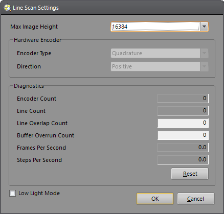
Line Scan Settings Controls
To display the Line Scan Settings dialog, click Line Scan Settings from the Sensor menu.
-
Max Image Height: Specifies the maximum number of pixel rows used to construct the image, and the maximum number of image buffers, for line scan vision systems.
Vision System Max Image Height In-Sight 5604 2048 (default)
4096
8192
In-Sight 9902L 2048
4096 (default)
8192
12288
16384
Note:- Adjusting the Max Image Height setting of a line scan vision system requires a reboot of the vision system, and will erase the current job on the vision system. Save or backup your job before continuing.
- The default number of image buffers allocated to the vision system at start up is dependent on the vision system's resolution and RAM size. Adjusting the Max Image Height setting may increase or decrease the maximum number of image buffers available to the vision system. If needed, use the Image Buffers dialog to modify the number of image buffers allocated to the vision system at start up.
- When using a 5604 line scan vision system configured to a Max Image Height of 8192, if the Width of the Region of Interest of a Vision Tool must be set to a Width of greater than 3072, the region must be set by either manually entering the region values through the Formula Bar, or a separate Controls or Structures function must be created and referenced in place of the tool's internal Region parameter.
-
When using a line scan vision system, the Region of Interest (ROI) Width has a maximum limit when entered in a Vision Tool property sheet. If you need to set the ROI Width to a higher value, you must either manually enter the region value in the Formula Bar or create a separate Controls or Structure function and reference it in place of the tool’s Region parameter.
Vision System Maximum Resolution Max Image Height Maximum Width in Property Sheet In-Sight 5604 1024 x 8192 8192 3072 In-Sight 9902L 2048 x 16384 8192 and greater
6144 1024 x 16384 4096 and greater 3072
-
Hardware Encoder
Note: To modify the Encoder Type or Direction, the Line Trigger Type parameter in the AcquireImage property sheet must be set to Hardware Encoder, the line scan vision system must be Offline and the user must have Full Access.-
Encoder Type: Specifies the type of hardware encoder used to trigger line acquisitions: Single (default) or Quadrature.
Note:- When the Encoder Type is set to Single, the single line encoder must be wired to the first encoder input; connecting the line to the second input has no effect.
- Quadrature Encoders provide direction information and require two high-speed inputs.
-
Direction: Specifies which direction should be considered the forward direction of the quadrature encoder: Positive (default) or Negative. The line scan vision system uses the Direction to determine the correct operating direction. Steps that are reverse direction are considered invalid and result in the current frame being aborted.
Note: This control is disabled when the Encoder Type is set to Single.
-
-
Diagnostics
- Encoder Count: Displays the number of hardware encoder steps (or microseconds for a software encoder).
- Line Count: Displays a running total of acquired lines since the counters were last reset.
- Line Overlap Count: Displays the number of lines lost due to excessive encoder rates.
- Buffer Overrun Count: Displays the number of times the line scan vision system ran out of image buffers.
- Frames Per Second: Displays the number of frames acquired per second.
-
Steps Per Second: Displays the number of steps that arrive from the external hardware encoder per second.
Note: If a software encoder is used, the value displayed is the number of microseconds per second. -
Reset Button: Resets all diagnostic statistics to zero.
Note: All diagnostic statistics are reset when the Reset button is clicked or if the line scan vision system is placed Online or Offline.
- 1K Resolution (Low Light Mode): Increases light sensitivity and decreases the standard area image to 1024 pixels wide. This option is only supported on the In-Sight 9902L line scan vision system.