Serial Port Settings Dialog
The Serial Port Settings dialog configures the active In-Sight vision system for serial communications. Input strings are read into the spreadsheet over the serial port using the ReadSerial function. Output strings are sent from the spreadsheet over the serial port using the WriteSerial function.
- The vision system must be Online to send/receive serial data.
- DeviceNet is only available on In-Sight vision systems using In-Sight firmware 4.x.x, and is not available on In-Sight vision systems running In-Sight firmware 5.1.0 and later. For a complete list of models and supported firmware versions, see Firmware Versions .
- In-Sight Micro 1000 series vision systems only support serial communication when connected to the CIO-MICRO or CIO-MICRO-CC I/O module.
- There are two options for enabling serial communication for the In-Sight 70xx - 74xx series vision system: using the Breakout cable or using the CIO-MICRO or CIO-MICRO-CC I/O module. When connected to the Breakout cable (and there is no connection to an I/O module), the vision system allows one discrete input line and one discrete output line to be configured as Serial Receive and Serial Transmit, respectively.
- In-Sight 8000 series vision systems only support serial communication when connected to the CIO-MICRO I/O module.
- The CIO-WENET Ethernet I/O module does not support serial communication.
- In job deployment environments where In-Sight Explorer or the VisionView application are monitoring inspections, if the job depends on a Soft Event (e.g., configured as a Timer function) to trigger a spreadsheet event, it may cause the inspection of an image to be delayed if it is triggered shortly before the acquisition cycle completes. If the job file is large (i.e., it contains many Vision Tools, such as Pattern Match, Flaw Detection or InspectEdge tools, in addition to other job logic), the update required by In-Sight Explorer or VisionView may prevent an image from being inspected until the display update is queued. For applications that require exact timing (e.g., measured in the 10s of milliseconds), this update might delay the determination of pass/fail results and the transmission of results to the next station (e.g., a PLC or motion controller) in the inspection process. To avoid delayed inspections in these application environments, Cognex recommends Soft Events not be used.
Configure the Serial Port Settings
- On the Sensor
menu, click Serial Port Settings.
-
If connected to an I/O module, click the I/O Module button to open the I/O Module Configuration dialog and configure the I/O module. Press the OK button to close the I/O Module Configuration dialog and return to the Serial Port Settings dialog.
Note:- After the first successful connection between the vision system and an I/O module, an "(attached)" message is displayed next to the I/O module that is physically attached to the sensor.
- If CIO-MICRO, CIO-MICRO-CC or CIO-WENET is the selected I/O module, when the OK button is clicked, the vision system attempts to establish EtherNet/IP communication with the module, using the specified IP address. If the IP address does not exist on the network, if EtherNet/IP is not enabled on the module, or if another device already has an EtherNet/IP connection to the module, an error message will appear.
-
Configure the serial settings. The available settings are listed in the following table:
Feature Direct I/O / CIO-1350 CIO-1400 CIO-14501 CIO-14601 CIO-MICRO CIO-MICRO-CC CIO-WENET1 Baud Rate2
4800
9600
19200
38400
57600
115200
2400
4800
9600
19200
38400
57600
115200
1200
2400
4800
9600
19200
38400
57600
115200
1200
2400
4800
9600
19200
38400
57600
115200
4800
9600
19200
38400
57600
115200
4800
9600
19200
38400
57600
115200
Disabled
Data Bits
7, 8
8
7, 8
7, 8
7, 8
7, 8
Disabled
Stop Bits
1, 2
1
1, 2
1, 2
1, 2
1, 2
Disabled
Parity
None
Even
Odd
None
Even
Odd
None
Even
Odd
None
Even
Odd
None
Even
Odd
None
Even
Odd
Disabled
Handshake
None
Xon/Xoff
Hardware
None
Xon/Xoff
Hardware
None
Xon/Xoff
Hardware
None
Xon/Xoff
Hardware
None
Xon/Xoff
Hardware
None
Xon/Xoff
Hardware
Disabled
Mode
Text
NativeDeviceNet
Motoman
Kuka
Unused
Text
NativeDeviceNet
Motoman
Kuka
Unused
Text
NativeDeviceNet
Motoman
Kuka
Unused
Text
NativeDeviceNet
Motoman
Kuka
Unused
Text
NativeDeviceNet
Motoman
Kuka
Unused
Text
NativeDeviceNet
Motoman
Kuka
Unused
Disabled
1The CIO-1450, CIO-1460 and CIO-WENET I/O modules are obsolete and no longer available for purchase, however these modules are still supported within In-Sight Explorer for backward compatibility only.
2DeviceNet supports a maximum Baud Rate of 57600. - Click the OK button.
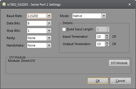
Serial Port Settings Dialog Controls
-
Baud Rate: 1200, 2400, 4800, 9600, 19200, 38400, 57600 or 115200.
Note: DeviceNet supports a maximum Baud Rate of 57600. - Data Bits: 7 or 8.
- Stop Bits: 1 or 2.
- Parity: None, Even, or Odd.
-
Handshake: None, Xon/Xoff, or Hardware.
Note:- The Handshake drop-down menu is always enabled, regardless of the configuration. Most In-Sight vision systems only support hardware handshaking if the vision system is connected to an I/O Module. Please refer to your vision system's installation manual to determine the physical connection requirements needed to enable hardware handshaking.
- If a large amount of data is to be transmitted, it is recommended that the Handshake parameter be set to Xon/Xoff to ensure that handshaking is used and data is not lost.
-
Mode: Sets the serial protocol to use.
Mode
Description
Text
Standard ASCII protocol for sending/receiving text strings.
Native
Custom ASCII protocol for controlling In-Sight from any remote serial device.
DeviceNet
Protocol for communicating with Allen-Bradley PLC.
Note: The DeviceNet setting requires a third-party RS-232-to-DeviceNet Gateway adapter. This setting is available for legacy installations and should not be used in new applications, unless the RS-232-to-DeviceNet Gateway converter has been thoroughly tested to verify it is suitable for the application.Motoman
Protocol for communicating with Motoman MRC, MRC-II, and XRC robot controllers operating in DCI mode.
Kuka
Protocol for communicating with Kuka KR C2 and KR C2 Edition 2005 robot controllers.
Unused
Closes the serial port so that no commands or data can be sent or received.
- Details: When Mode is set to DeviceNet, Native Mode, or Text Mode, the Details portion of the dialog will display, allowing you to configure input/output terminator characters and data packet sizes specific to the selected Mode.
Text Mode Details
The Text Mode Details defines the terminator characters to use for text-mode serial communications. These details are available only when Mode is set to Text.
- Fixed Input Length: Reads a fixed number of characters before triggering an event.
- Input Terminator: The ASCII value interpreted by In-Sight as the end of an incoming string. The default is 13 (carriage return). Input Terminator is disabled if Fixed Input Length is selected.
- Output Terminator: The ASCII value that In-Sight adds to each output string to mark the end of the transmitted string. The default is -1; -1 specifies "CRLF" (carriage return/line feed), and 0 specifies "no terminator".
Native Mode Details
The Native Mode Details sets the terminator characters for Native Mode serial communications. These details are available only when Mode is set to Native.
- Fixed Input Length: Reads a fixed number of characters before triggering an event.
- Input Terminator: The ASCII value interpreted by In-Sight as the end of an incoming string. The default is 13 (carriage return). Input Terminator is disabled if Fixed Input Length is selected.
- Output Terminator: The ASCII value that In-Sight adds to each output string to mark the end of the transmitted string. The default is -1; -1 specifies "CRLF" (carriage return/line feed), and 0 specifies "no terminator".
DeviceNet Details
The DeviceNet Details sets the packet size for DeviceNet connections to an In-Sight vision system using the optional DeviceNet Interface Module. These details are available only when Mode is set to DeviceNet.
-
Input Packet Size: Sets the expected packet size to be received through the DeviceNet Interface Module, in bytes. The setting must agree with the MaxWidth value in the RS232-to-DeviceNet configuration.
-
Output Packet Size: Sets the packet size to send out through DeviceNet Interface Module, in bytes. The setting must agree with the Transmit Width value in the RS232-to-DeviceNet configuration.
-
Trigger On First Byte: Triggers an acquisition when the first byte is received. The Trigger parameter must be set to External in the AcquireImage property sheet.
Note: When Trigger on First byte is enabled, and the In-Sight vision system is triggered, a previous image may be displayed and cell data may display data from the previous spreadsheet update.