Communicate with a Mitsubishi Automation Controller via iQ Sensor Solution
Overview
This topic describes how to configure the iQ Sensor Solution for In-Sight vision systems, and transfer data between a vision system and a Mitsubishi Automation Controller using the GX Works software. The examples in this topic were written assuming the following components are being used:
- In-Sight vision system running the following firmware version:
- 4.x.x
- 5.7.4 or later
-
Mitsubishi Automation Controller : iQ-R, iQ-F, Q and L series (3E Frame)
Note: FX series (1E Frame) is not supported on iQ Sensor Solution. - Mitsubishi GX Works software
- GX Works2 (SWnDNC-GXW2-E), version 1.492 or later (Q and L series)
- GX Works3, version 1.055H or later (iQ-R and iQ-F series)
- Cognex In-Sight Profile Language Package (English = CognexInsight_en.ipar; Japanese = CognexInsight_ja.ipar) included within In-Sight Explorer 4.x.x, or 5.7.4 or later.
- iQ Sensor Solution is only available on In-Sight vision systems using In-Sight firmware 4.x.x, or 5.7.4 or later.
- If a PLC project created in the English version of GX Works is downloaded to the PLC, and then uploaded to a Japanese version of GX Works, In-Sight 5000 and In-Sight 70xx - 74xx series vision systems will be missing their icons and descriptive information. This issue also occurs if the process is reversed, i.e. the PLC project is created in the Japanese version of GX Works and then uploaded to an English version of GX Works. It is recommended that you keep PLC projects within the same language of GX Works.
- For more information on Mitsubishi iQ Sensor Solution, refer to Mitsubishi's iQ Sensor Solution Reference Manual.
Mitsubishi iQ Sensor Solution
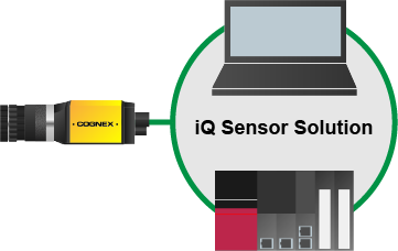
Mitsubishi iQ Sensor Solution is a factory protocol that enables the GX Works software to control In-Sight vision systems over the SLMP Scanner protocol. For more information, see Configure In-Sight Vision Systems for SLMP Communications. With the iQ Sensor Solution, GX Works is able to discover vision systems on the network, read/write the vision system's SLMP Scanner parameter settings and monitor the status of a vision system.
Discovering In-Sight Vision Systems on GX Works
The following procedure assumes that the In-Sight vision system has not previously configured for SLMP Scanner and is connected to the same Ethernet subnet as a supported Mitsubishi Automation Controller.
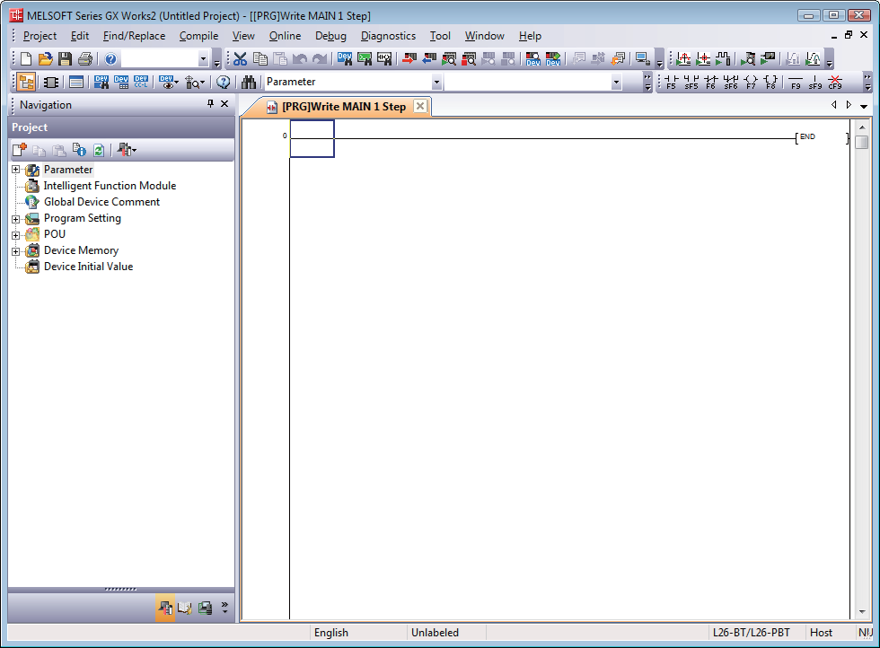
- Launch the GX Works software.
-
Create a new project in GX Works.
- From the Tool menu, select Register Profile. The Register Profile window opens.
-
Navigate to the Cognex In-Sight Profile Language Package (English = CognexInsight_en.ipar; Japanese = CognexInsight_ja.ipar), and click Register.
Note: By default, the Cognex In-Sight Profile Language Package is installed to: C:\Program Files (x86)\Cognex\In-Sight\In-Sight Explorer x.x.x\Factory Protocol Description\ESPP. -
Select Parameter --> PLC Parameter on the Project view. The L Parameter Setting window is displayed.
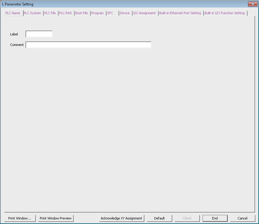
-
Select the Built-in Ethernet Port Settings tab.
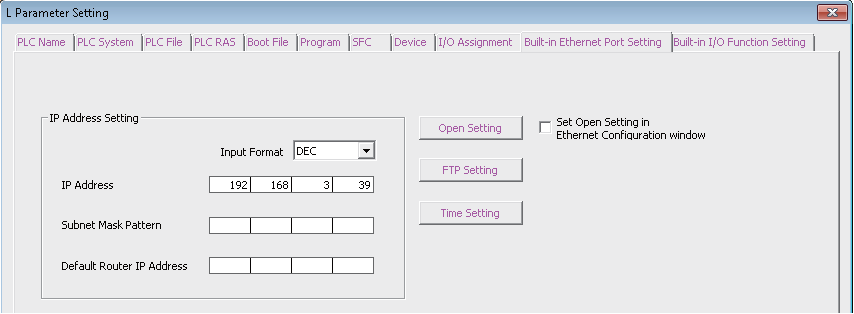
-
Check the Set Open Setting in Ethernet Configuration window checkbox. The following message will be displayed.
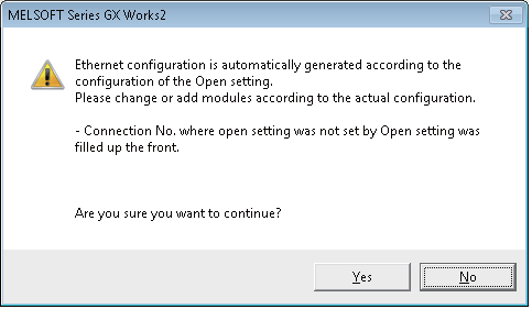
-
Click Yes; the Open Settings button will be changed to the Ethenet Conf. button.
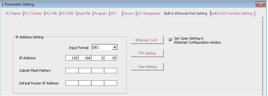
-
Click the Ethernet Conf. button. The Ethernet Configuration window will be displayed.
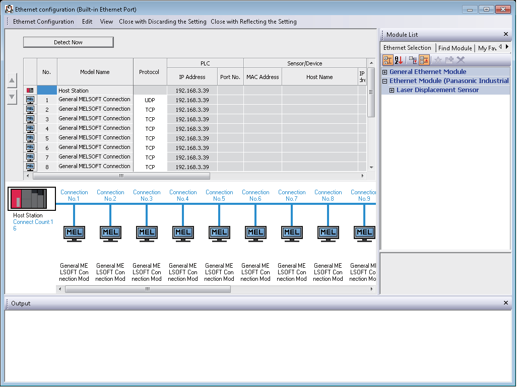
-
Select Ethernet Configuration --> Online --> Detect Now; the following message is displayed.
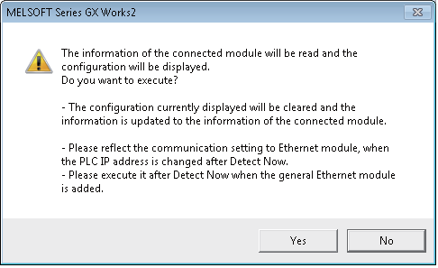
-
Read the message and click Yes. The actual system configuration is reflected on the Ethernet Configuration window.
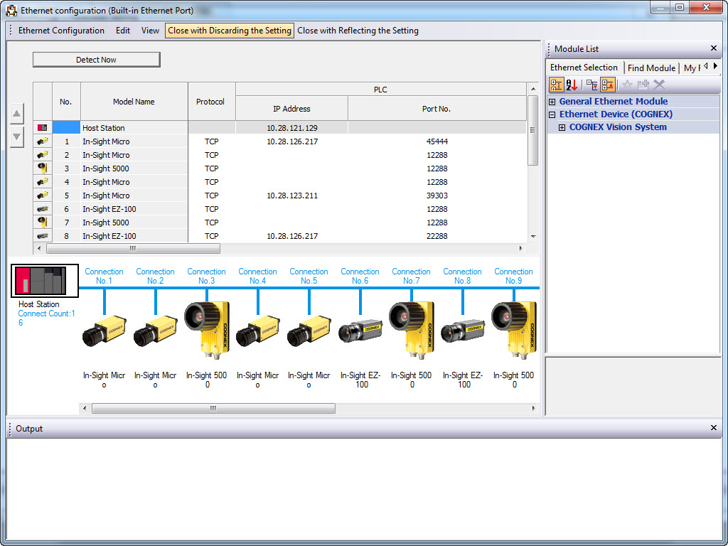
- Select Close with Reflecting the Setting. The settings on the Ethernet Configuration window will be saved, and the system configuration setting is completed.
- Up to 16 In-Sight vision system may be displayed (in ascending order of their IP addresses) on the Ethernet Configuration window after executing the automatic detection of connected devices.
- If the Detect Now button is pressed, and a vision system in the network is not iQSS-compatible, the vision system will not appear in the Ethernet configuration window. If a vision system is iQSS-compatible but no profile was previously added to GX Works, "Module With No Profile Found" will be displayed.
- Error information is displayed on the Output window when there is an error in the system configuration after executing the automatic detection of connected devices. Double-click the error on the Output window and correct the error at the error jump destination.
- For troubleshooting, refer to Mitsubishi's iQ Sensor Solution Reference Manual.
Reflect the Communication Settings to In-Sight Vision Systems
The communication settings, such as the IP address, can be reflected to the In-Sight vision system. Execute this feature after adding/deleting or changing the settings of vision systems.
- From GX Works, open the Ethernet Configuration window. (To display this window, refer to the Discovering In-Sight vision systems on GX Works section).
- Select the target In-Sight vision system and configure the communication settings.
-
Right-click the target vision system on the device map area.
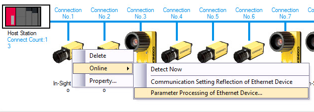
- Select Online --> Communication Setting Reflection of Ethernet Device. The communication settings will be now reflected to the selected vision system.
Reading and Writing SLMP Scanner Parameters
- From GX Works, open the Ethernet Configuration window. (To display this window, refer to the Discovering In-Sight vision systems on GX Works section).
-
Right-click the target In-Sight vision system on the device map area.
-
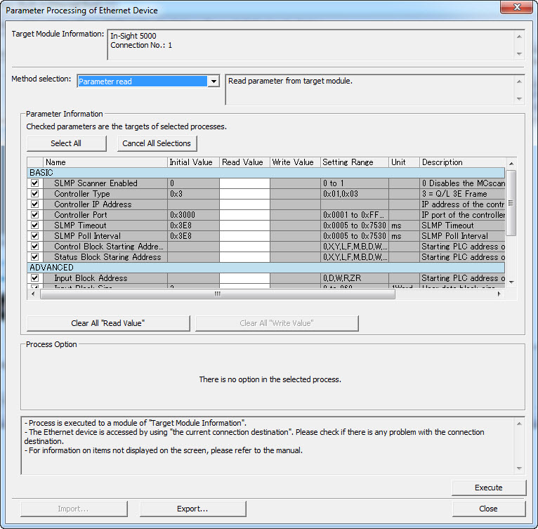
Select Online --> Parameter Processing of Ethernet Device. The Parameter Processing of Ethernet Device window will be displayed.
Reading Parameters
- To read the vision system's parameters, from the Method selection drop-down list, select Parameter read.
- Confirm that the checkboxes for the parameter to be read are checked.
- Click the Execute button. The vision system's parameter values will be displayed in the Read Value column.
Writing Parameters
- To write the vision system's parameters, from the Method selection drop-down list, select Parameter write.
- Confirm that the checkboxes for the parameter to be written are checked.
- Enter values in the Write Value column.
- Click the Execute button. The new parameter values will now be written to the vision system.
Parameters
| ID | Name | Type | Size (Byte) | Description | Corresponding GUI on In-Sight Explorer |
|---|---|---|---|---|---|
| 1 (4.x.x) | SLMP Scanner Enable1 | Byte | 1 |
Enables the SLMP Scanner service on the vision system. 0 = Disabled (default); 1 or greater =Enabled. Note: The vision system must be restarted to enable the SLMP Scanner service.
|
Network Settings Dialog |
| 1 (5.7.4 or later) | Enabled Protocol1 | Byte | 1 |
Enables the SLMP Scanner or CC-Link IE Field Basic service on the vision system. 0 = None (default), 1 = SLMP Scanner, 2 = CC-Link IE Field Basic. Note: The vision system must be restarted to enable the selected protocol.
|
|
| 2 | Controller Type | Enum | 1 | Specifies the type of Mitsubishi PLC/MC to communicate with: iQ-R/Q/L Series (3E Frame), iQ-F Series (3E Frame) or FX Series (1E Frame)1. Default = iQ-R/Q/L Series (3E Frame). |
SLMP Scanner Settings Dialog |
| 3 | Controller IP Address | String | Specifies the IP address of the PLC/MC that In-Sight vision system will be connected to. | ||
| 4 | Controller Port | Word | 2 | Specifies the TCP port number, in decimal (1 - 65535) format, of the SLMP channel that will be used by the PLC/MC (default = 12288 in Dec). | |
| 5 | SLMP Timeout | Word | 2 | Specifies the timeout (5 to 30000; default = 1000), in milliseconds, for a response from the PLC/MC to an SLMP message. | |
| 6 | SLMP Poll Interval | Word | 2 | Specifies the amount of time (5 to 30000; default = 1000), in milliseconds, between successive polls of the Vision Control block on the PLC/MC. | |
| 7 | SLMP Control Address | String |
The starting PLC/MC address of the vision control data block.
|
Device Addressing Tab | |
| 8 | SLMP Status Address | String |
The starting PLC/MC address of the vision status data block.
|
||
| 9 | SLMP Input Address | String |
The starting PLC/MC address of the inspection results data block.
|
||
| 10 | SLMP Input Size | Word | 2 |
Specifies the size of the data block that will be communicated with the PLC/MC. 2 devices2 + Input Data length (in words) (Maximum: 960 words) |
|
| 11 | SLMP Output Address | String |
The starting PLC/MC address of the user data block.
|
||
| 12 | SLMP Output Size | Word | 2 |
Specifies the size of the data block that will be communicated with the PLC/MC. 5 devices3 + Output Data length (in words) (Maximum: 960 words) |
|
| 13 | SLMP Command Address | String |
The starting PLC/MC address of the command string. None (default); D - Data Register; W - Link Register; R - File Block Register; ZR - File Register |
||
| 14 | SLMP Command Size | Word | 2 |
Specifies the size of the data block that will be communicated with the PLC/MC. 0 - 960 (default = 0) |
|
| 15 | SLMP Command Result Address | String |
The starting PLC/MC address of the command result data.
|
||
| 16 | SLMP Command Result Size | Word | 2 |
Specifies the size of the data block that will be communicated with the PLC/MC. 0 - 960 (default = 0) |
|
|
1 FX series (1E Frame) is not supported on the iQ Sensor Solution. 2 2 devices (4 bytes/2 words) are used for the Job Load ID and User Length. 3 5 devices (10 bytes/5 words) are used for the Job ID, Acquisition ID, Inspection ID, Inspection Result Code and Inspection Result Length. |
|||||
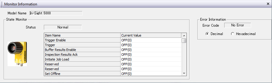
Monitoring the Status of In-Sight Vision Systems
- Launch the GX Works software and open a project that has the specified network configured.
- From the Diagnostics menu, select Sensor/Device Monitor. The Module Selection (Sensor/Device Monitor) window will be displayed.
-
Click OK; the Status of vision systems connected to the Built-in Ethernet port LCPU will be displayed on the Sensor/Device Monitor window.
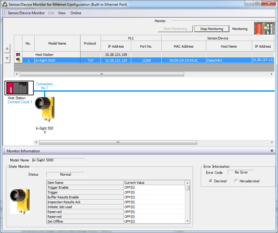
-
Select the desired vision system from the "list of devices" or "device map area". The status of the vision system will be displayed on the Monitor Information window.
Note: Only one vision system can be monitored in the Ethernet Configuration window at a time.