Configure Discrete I/O Lines
-
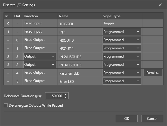
From the Tools Menu, click Discrete I/O Settings.
-
Select an input or output line to configure. For more information, see In-Sight D900 Series I/O Lines.
Note: TRIGGER is reserved for acquisition trigger input and cannot be configured. -
If the line supports a bi-directional I/O, select Input or Output from the Direction drop-down.
Note: The In-Sight D900 series vision system supports bi-directional high-speed outputs and general-purpose inputs for HSOUT 2 / IN 2 and HSOUT 3 / IN 3. These lines are configured as outputs by default. -
You can customize the default line Name by entering a new name specific to your application. The name does not change the functionality of the line and cannot be referenced.
-
Choose a Signal Type for the selected input line. Each input line can be configured for one of the following functions:
Input Signal Type Description Programmed
(default)
Enables a ReadDiscrete function in the spreadsheet to control the state of this input line. Event Triggers an event. To update the spreadsheet, the spreadsheet must contain an Event structure with its Trigger parameter set to this discrete input line number. Online Forces the In-Sight vision system Online or Offline. This input type may not be used on more than one input line simultaneously. -
Click the Details button for the selected input line, if detailed settings are available for the specified Input Signal Type. For more information, see Configure Discrete Input Details.
-
Choose a Signal Type for the selected output line. Each output line can be configured for one of the following functions:
Output Signal Type Description Programmed
(default)
Enables a WriteDiscrete function in the spreadsheet to control the state of this output line. High Forces the output to HIGH (1). Low Forces the output to LOW (0). Acquisition Start Signals the vision system has initiated an acquisition. Acquisition End Signals the completion of vision system acquisition. Acquisition Missed Signals that an acquisition trigger was received before an Acquisition End signal was sent, or that no image buffer was available for image acquisition when an acquisition trigger was received.
Note: The Trigger Mode parameter in the AcquireImage property sheet must be set to Camera to use the Acquisition Missed output.Strobe The rising or falling edge of the signal can be used to trigger a strobe.
Note: The In-Sight D900 series vision systems only support the Strobe signal type on the HSOUT 1 line.Rising Edge - NPN Configuration: If the Strobe/Light Control Trigger in the Output Details dialog is set to Rising Edge, the signal is HIGH when the image sensor is being exposed, otherwise the signal is LOW. Always pulsed for the duration of the exposure.
- PNP Configuration: If the Strobe/Light Control Trigger in the Output Details dialog is set to Rising Edge, the signal is LOW when the image sensor is being exposed, otherwise the signal is HIGH. Always pulsed for the duration of the exposure.
Falling Edge - NPN Configuration: If the Strobe/Light Control Trigger is set to Falling Edge, the signal is LOW when the image sensor is being exposed, otherwise the signal is HIGH. Always pulsed for the duration of the exposure.
- PNP Configuration: If the Strobe/Light Control Trigger is set to Falling Edge, the signal is HIGH when the image sensor is being exposed, otherwise the signal is LOW. Always pulsed for the duration of the exposure.
Job Completed Signals each time the spreadsheet has completed an update. Online Signals when the vision system is Online or Offline. HIGH (1) when the vision system is Online, LOW (0) when the vision system is Offline. Busy HIGH (1) when the vision system is running a job or responding to user input, LOW (0) when the vision system is idle. Job Load OK Signals the job loaded successfully. Job Load Fail Signals the failure of a job load. - Click the Details button for the selected output line, if detailed settings are available for the specified output Type. For more information, see Configure Discrete Output Details.
-
Optionally, specify the Debounce Duration time for all input lines in microseconds (0 - 1000000, default = 50). This setting delays the recognition of a valid input signal by the amount of time specified.
Note: The Debounce Duration time specified in the Configure Discrete I/O Lines dialog doesn’t apply to the TRIGGER line. To configure the Debounce Duration time for the TRIGGER line, use the AcquireImage function. For more information, see AcquireImage. -
Optionally, check De-Energize Outputs While Paused to de-energize the outputs when the vision system is placed Offline.
Note:-
When the vision system is Online, the De-Energize Outputs While Paused behaves as follows:
- Regardless whether it is enabled or disabled, Outputs are activated by their configured signal type.
-
When the vision system is Online, but in the Paused state, the De-Energize Outputs While Paused behaves as follows:
- When it is disabled, the Outputs are activated by their configured signal type.
- When it is enabled, the Outputs are always inactive.
- If the De-Energize Outputs While Paused checkbox is enabled, and you place the vision system Online, output line(s) configured using the Discrete I/O Settings dialog are restored. However, Output line(s) configured using the WriteDiscrete function are not restored. In this scenario, the function's specified Event must occur for the output line(s) to be restored. For more information, see WriteDiscrete.
-
- Click OK to accept the changes (changes are saved to flash memory), or click Cancel to undo the changes.