AcquireImage
The AcquireImage function specifies the parameters for capturing a digital image and transferring it to the In-Sight vision system's processing memory.
In-Sight vision systems capture all images using asynchronous reset and progressive scan. Greyscale vision systems produce 8-bit images, while color vision systems (indicated with a C suffix) produce 24-bit images. The image acquisition process begins within approximately 250µs for all vision systems, and proceeds as follows:
- The image sensor integrates light for the duration of time specified by the Exposure parameter.
- The image accumulated in the image sensor is transferred, row-by-row, into a serial shift register.
-
For every row transfer, the sensor clocks the shift register, pixel-by-pixel, out of the image sensor through the following path:
Video amplifier -> Gain and Offset -> Analog-to-digital converter -> Vision processor memory
The memory buffer containing the acquired image is represented in the spreadsheet as an Image data structure. The Image data structure returned by AcquireImage is in turn referenced by other In-Sight spreadsheet functions that process image regions. Any function that directly or indirectly depends on acquired image data is forced to update when a new image is acquired. This relationship between the input image and other functions in the spreadsheet is what drives the execution of vision tasks on In-Sight vision systems. For more information on dependencies and cell execution order, see Spreadsheet Cell Execution.
When a spreadsheet is initially created, an AcquireImage function will automatically be added and located in cell A0. Most Vision Tool functions, as well as many other functions, take advantage of this by specifying an absolute reference to cell A0 as their default image source. For more information, see Cell References.
AcquireImage Inputs
| Parameter | Description | ||||||||||||||||||||||||||||||||||||||||||||||||||||||||
| Trigger Mode |
Defines how the device will be triggered to acquire an image. Note: Trigger Mode is used with the dedicated acquisition trigger input line. For more information, see Configure Discrete I/O Lines.
|
||||||||||||||||||||||||||||||||||||||||||||||||||||||||
| Trigger Interval |
Defines an interval, in milliseconds, between acquisitions (0-10000; default = 500). This setting is dependent on the amount of time the spreadsheet takes to complete processing the image. For example, if the Trigger Interval is set to 5,000 milliseconds, the device acquires an image every 5,000 milliseconds, provided the spreadsheet completes its image processing within 5,000 milliseconds. If not, the device acquires an image as soon as it completes processing the image. Note: The Trigger Mode must be set to Timer Interval to enable this parameter.
|
||||||||||||||||||||||||||||||||||||||||||||||||||||||||
| Debounce (ms) |
Defines the amount of time (0-65.535 milliseconds; default = 0.5) that the input trigger must remain active to be recognized as a valid trigger, when the Trigger Mode property is set to Camera. Note: The Trigger Mode must be set to Camera to enable this parameter.
|
||||||||||||||||||||||||||||||||||||||||||||||||||||||||
| Delay (ms) |
Defines the delay (0-10000 milliseconds; default = 0) between the time that a trigger to acquire an image is received, and the time device begins the image acquisition. No additional triggers are accepted during this delay period, and any received triggers during this period will result in a Missed Trigger event. |
||||||||||||||||||||||||||||||||||||||||||||||||||||||||
| Exposure (ms) |
Defines the exposure time. When the device receives an image acquisition trigger signal, light is integrated into the image sensor array for the specified duration. Shorter durations are better suited for stopping motion, but may require larger lens apertures or higher Gain settings to achieve sufficient image intensity.
The In-Sight illumination accessory has a maximum strobe pulse width that is dependent on the Intensity, LED ring light color, vision system resolution and number of rows acquired. Up to a certain Exposure time, the illumination accessory will illuminate for the specified Exposure time. If the Exposure time exceeds the maximum strobe pulse width, the LED ring light will only illuminate for the maximum strobe pulse width. See the following table for the calculated maximum strobe pulse width for the supported LED ring light, intensity, and device type combinations. Note: When working with color vision system models (In-Sight D902C, D905C), use white LED ring light only.
Note: At Exposure times greater than the maximum strobe pulse width, a lower Intensity may result in brighter images, due to increased LED efficiency at a lower current.
|
||||||||||||||||||||||||||||||||||||||||||||||||||||||||
| Offset |
Defines a Direct Current (DC) level that is added or subtracted from the device's analog signal before the analog-to-digital conversion. The Offset affects the image's brightness and darkness, while maintaining the dynamic range within the image. (0 to 255; default = 0)
|
||||||||||||||||||||||||||||||||||||||||||||||||||||||||
| Gain | Defines the gain of the amplifier stage that precedes the analog-to-digital conversion.
|
||||||||||||||||||||||||||||||||||||||||||||||||||||||||
| Orientation |
Defines the orientation of the image.
|
||||||||||||||||||||||||||||||||||||||||||||||||||||||||
| Start Row |
Defines the first row to be transferred from the image sensor into memory on the device. Note: The value of this property is locked to 0 when using an In-Sight D900 series vision system, and cannot be changed.
|
||||||||||||||||||||||||||||||||||||||||||||||||||||||||
| Number of Rows |
Defines the number of image sensor rows to be transferred into memory on the device. This is used to create partial image acquisitions, where only a specified number of image rows are used to create the output image. Note:
This property cannot be modified when using an In-Sight D900 series vision system, and always takes the maximum number of rows supported by the device:
|
||||||||||||||||||||||||||||||||||||||||||||||||||||||||
| Image Buffers |
Defines the number of buffers used for image acquisition, based on the resolution and RAM of the vision system. Note:
This property cannot be modified when using an In-Sight D900 series vision system, and takes a value depending on the device type:
|
||||||||||||||||||||||||||||||||||||||||||||||||||||||||
| Illumination |
The following parameters are used to configure light settings. Note: Only the Strobe Start and Strobe Polarity parameters are available when using an In-Sight ViDi PC device.
|
||||||||||||||||||||||||||||||||||||||||||||||||||||||||
| Focus |
The following parameters are used to configure focus settings. Note: The Focus parameter is only available for In-Sight D900 series vision systems.
|
||||||||||||||||||||||||||||||||||||||||||||||||||||||||
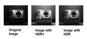
| High Dynamic Range |
HDR (High Dynamic Range) provides better contrast and more brightness for darker regions of an image. This effect is completed in a single acquisition.
Note: HDR is supported only on monochrome In-Sight vision systems. It is not available for color vision systems (In-Sight D902C, D905C).
The following parameters determine the HDR method and kernel size.
|
||||||||||||||||||||||||||||||||||||||||||||||||||||||||
AcquireImage Outputs
Returns an Image data structure. The cell will return #ERR if an image has not yet been acquired for the job; simply trigger an acquisition (press the Trigger Once button or press F6).
| In-Sight Model | Resolution | Greyscale/Color | Bit depth | Number of grey levels or colors | Frames Per Second (FPS)* |
| D902 | 1920 x 1200 | greyscale | 8-bit | 256 | 51 |
| D902C | 1920 x 1200 | color | 24-bit | 16 million | 34 |
| D905 | 2448 x 2048 | greyscale | 8-bit | 256 | 26 |
| D905C | 2448 x 2048 | color | 24-bit | 16 million | 16 |
| *Maximum frames per second are job-dependent, based on the minimum exposure for a full image frame capture using the dedicated acquisition trigger, and assumes there is no user interface connection to the vision system. | |||||
ApplyAcquisitionSettings
When you drag and drop a parameter from the AcquireImage property sheet to the spreadsheet, an ApplyAcquisitionSettings function is added to the spreadsheet, which allows you to edit acquisition parameters without opening the AcquireImage function and changes the acquisition parameters' value at runtime. On the AcquireImage property sheet, the dragged-and-dropped parameter displays a blue exclamation icon. This icon indicates that the parameter is referenced by an ApplyAcquisitionSettings function, and when you hover over the icon, the ApplyAcquisitionSettings function's cell location is displayed as a tip.
![]()
- The AcquireImage property sheet also displays a blue exclamation icon when an associated parameter is dragged and dropped from the ApplyAcquisitionSettings property sheet. For more information, see ApplyAcquisitionSettings
- If a parameter is referenced by multiple ApplyAcquisitionSettings functions, the icon indicates the ApplyAcquisitionSettings functions' cell locations (up to five locations).
-
If you uncheck a parameter on the ApplyAcquisitionSettings property sheet, the associated parameter's blue exclamation icon no longer displays in the AcquireImage property sheet.
GigE Feature Access
To open the GigE Feature Access dialog, click the GigE Feature Access button in the AcquireImage property sheet. The GigE Feature Access dialog is used to examine or modify the XML-defined properties for the GigE Vision camera you are using.
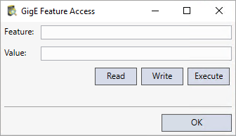
- Enter the XML node name in the Feature field.
- Click the Read button to read the value of the node and update the Value field.
- Click the Write button to attempt to write whatever value is in the Value field to the node.
-
Click the Execute button to attempt to execute the command feature specified in the Feature field.