3D-L4000 Series Vision System Wizard – Correction Settings
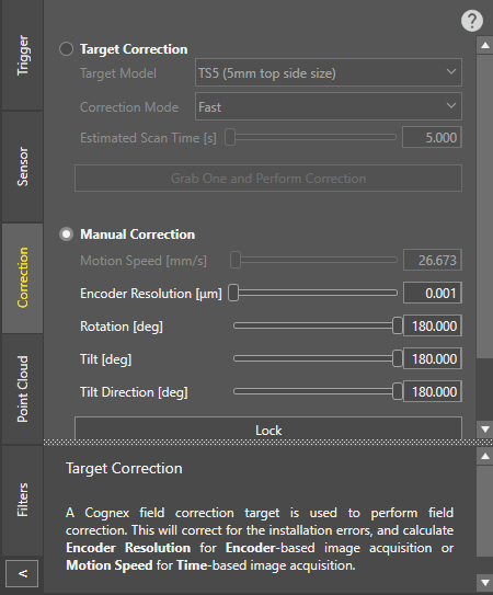
The 3D-L4000 Series Acquisition Wizard contains all the field correction settings for 3D-L4000 series vision systems on its Correction tab. The wizard offers two types of field correction: Target Correction and Manual Correction.
- Target Correction: When selecting this method, you must use a Cognex Correction Target Model to perform field correction. This method handles possible installation errors and also calculates the appropriate Encoder Resolution (in case of encoder-based image acquisition) or Motion Speed (in case of time-based image acquisition). This method is very accurate, and is able to compensate all possible sensor misalignments.
-
Manual Correction: When selecting this method, you must specify the identified installation errors (in terms of rotational angles) yourself. Likewise, you must set the appropriate Encoder Resolution (in case of encoder-based image acquisition) or Motion Speed (in case of time-based image acquisition) values manually.
Tip: Cognex recommends using Manual Correction either if you do not have any Cognex Correction Target Models, or because they cannot be used due to space limitations in the physical setup. After performing manual correction, Cognex recommends to Lock the correction to ensure that no settings affecting Field Correction will be modified accidentally later.
- Target Correction and Manual Correction are mutually exclusive. Selecting one of them automatically disables the settings of the other.
-
After Target Correction is performed, the Manual Correction settings will automatically be updated, allowing you to check the values determined by the target correction algorithm. You can also modify these settings afterwards without the need of performing Target Correction again: to do so, just switch from Target Correction to Manual Correction, and modify the setting you want to change. For example, in case of time-based acquisition, you can change the Motion Speed setting, if needed – just consider that acquisition accuracy will depend on how close actual motion is to the configured motion value.
| Setting | Description |
| Target Correction | |
| Target Model |
Allows you to select the Cognex Field Correction Target Model type used for correction. The model is defined based on the square edge length at the top of the truncated pyramid. Note:
|
| Correction Mode |
Allows you to select the mode for determining the correction parameters:
|
| Estimated Scan Time |
Defines the estimated duration of the scan (in seconds) required for target correction. The value range is 5 – 500, and the default value is 5. Tip: Specify a duration that is enough to cover the entire correction target end-to-end. If the estimated scan time is set too low, scanning will be incomplete, causing the field correction to fail. If it is set too long, the scan will have a low Y-resolution, making field correction less accurate.
|
| Grab One and Perform Correction | Start the acquisition of the specified Field Correction Target. If acquisition is successful, the correction settings get locked. If any errors occur, it is indicated in a pop-up window with further instructions. |
| Manual Correction | |
| Motion Speed (mm/s) |
Sets the speed along the motion of the system (in mm/s), such as the speed of a conveyor belt, motion stage or robot arm. Tip:
|
| Encoder Resolution |
Defines the resolution of the encoder used by the vision system (in um), corresponding to the distance between consecutive pulse outputs. Tip:
|
| Rotation |
Specifies the angle between the vision system and motion direction on the XY plane. In other words, it is the rotation along the Z axis required to align the device and the motion vector. The value range is -180 to 180, and the default value is 180. Note: This parameter is calculated automatically if Target Correction is enabled.
|
| Tilt |
Specifies the angle between the laser plane and the Z axis. Use this setting if the laser is not perpendicular to the base plane.. The value range is 0 to 180, and the default value is 180. Note: This parameter is calculated automatically if Target Correction is enabled.
|
| Tilt Direction |
Specifies the direction in which the device is tilted. This value is ignored if the tilt angle is 0. The value range is -180 to 180, and the default value is 180. Note: This parameter is calculated automatically if Target Correction is enabled.
|
| Lock |
Applies the configured correction settings, and locks the Correction tab. To modify any of the properties, unlock the Correction tab with the Unlock button. Note: You can export Manual Correction settings only if the settings are locked with the Lock button. At the same time, you cannot import any previously saved correction settings while the lock is active.
|
| Shared Options | |
| Import... |
Allows you to import an existing field correction configuration set for the configured vision system. Note: This button is enabled only if the correction settings are unlocked.
|
| Export... |
Allows you to export the field correction settings configured on the device, and reuse them on another vision system. The field correction configuration is saved into an *.ar file. Note: This button is enabled only if the correction settings are locked.
|
Once Field Correction is performed, the settings cannot be modified unless clicking the Unlock button, or performing a new correction. The results of the correction then appear under the Unlock button:
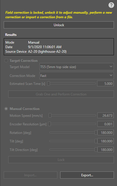
If the resulting RMS value of the correction is higher than expected, the Results table indicates it in red, and a pop-up warning will also appear at the top right corner of the screen. This error can occur if you:
- Use an incorrect Frustum model.
- Configure the Detection Zone incorrectly (so that, for example, the floor is also detected).
- Configure other acquisition settings incorrectly, so the Frustum could not be acquired by the vision system.