3D-L4000 Series Vision System Wizard – Trigger Settings

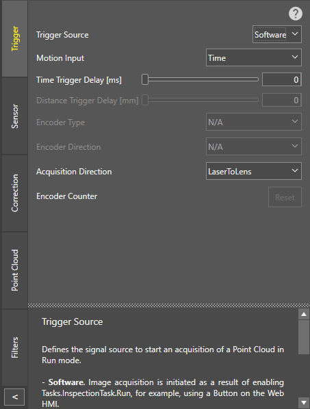
The 3D-L4000 Series Acquisition Wizard contains the triggering settings for 3D-L4000 series vision systems on its Trigger tab. These settings allow you to configure the trigger source and the motion/direction settings of the acquisition.

Setting Description
Trigger Source

Specifies the trigger source for the acquisition:

  • Software: Select this option if acquisition is manually performed, for example by clicking a Button in the WebHMI interface of the configured job.
  • Hardware: Select this option if acquisition is based on an external signal connected to the I/O interface.
  • Continuous: Select this option if you want the device to acquire image data continuously when set Online, until paused or taken Offline either by a PLC signal, or a Button in the WebHMI.
  • Industrial Ethernet: Select this option if you want to control the vision system exclusively with PLC signals.

    Note: This mode only works if the device is Online. When the vision system is Offline, this mode works the same as the Software setting.
Motion Input

Defines the acquisition driving logic for every profile:

  • Encoder: Profile acquisition is triggered by a physical encoder generating signals (or ticks) for acquisition.
  • Time: Profile acquisition is triggered at a fixed time interval by an internal clock generating fixed-frequency pulses.
Note: This setting affects field correction. Therefore, make sure to configure it before performing field correction on the device in the Correction tab.
Time Trigger Delay

Specifies a time delay (in milliseconds) between the trigger signal and the start of the acquisition. The value range is 010,000, and the default value is 0, meaning no time delay between the trigger signal and the acquisition.

Note: This setting is enabled only if Motion Input is set to Time.
Distance Trigger Delay

Specifies the amount of distance (in mm) between the trigger signal and the start of the point cloud acquisition. The value range is 010,000, and the default value is 0, meaning no distance-based delay between the trigger signal and the acquisition.

Note:
  • This setting is enabled only if Motion Input is set to Encoder.
  • The system will use a multiple of the Encoder Resolution closest to the specified value.
Encoder Type

Specifies whether the encoder signal used for acquisition is single or dual-channel:

  • Single Channel: Select this option for single-channel encoders. Such encoders can only detect the presence of the motion, but not its direction.

    Note: If this encoder type is selected, you do not have to set the Encoder Direction, as any motion (incremental or decremental) will trigger an acquisition.
  • Dual Channel: Select this option for dual-channel encoders. Such encoders can detect both the presence and the direction of the motion.

    Note: If this encoder type is selected, you must also specify the Encoder Direction. The vision system then performs an acquisition only if the detected motion has the same direction as specified with the Acquisition Direction setting.
Note: This setting affects field correction. Therefore, make sure to configure it before performing field correction on the device in the Correction tab.
Encoder Direction

Specifies how the encoder is physically connected to the vision system, affecting the motion direction that increases the Encoder Counter.

  • Laser to Lens: The Encoder Counter increases if the motion direction is from the cast laser to the vision system's lens.
  • Lens to Laser: The Encoder Counter increases if the motion direction is from the vision system's lens to the cast laser.

In both cases, the vision system must be static. This setting can only be configured before field correction is performed: after that, it is grayed out and can no longer be modified.

Note:
  • This setting is enabled only if Motion Input is set to Encoder, and Encoder Type is set to Dual Channel.
  • This setting affects field correction. Therefore, make sure to configure it before performing field correction on the device in the Correction tab.
Tip: Make sure that the Encoder Direction is specified correctly, based on the physical setup of the vision system. Otherwise, the generated point cloud will be mirrored along the motion direction.
Acquisition Direction

Specifies in which motion direction you want to acquire. This setting is independent of the Encoder Direction setting.

  • Laser to Lens: The vision system acquires image data if the motion direction is from the cast laser to the vision system's lens. Use this setting when the object is approaching the vision system from the side where laser is located.
  • Lens to Laser: The vision system acquires image data if the motion direction is from the vision system's lens to the cast laser. Use this setting when the object is approaching the vision system from the opposite side where laser is located.
Tip: By default, you can trigger acquisitions only in one direction. If you want to trigger acquisitions in both directions (that is, both toward and away from the vision system), change the Acquisition Direction setting after performing the first acquisition.
Encoder Counter

Indicates the current encoder position so that you can check if the encoder is wired correctly and working properly. The Encoder Counter always has a positive value that you can reset with the Reset button.

Note: The Encoder Counter works only if Motion Input is set to Encoder.