Use the BeadFind and BeadInspect Functions
This topic provides an overview of the BeadFind and BeadInspect functions and the basic steps of how to set up these two functions. For more information, see BeadFind and BeadInspect.
- BeadFind and BeadInspect functions are only available on In-Sight vision systems running In-Sight firmware 5.5.0 and later. For a complete list of models and supported firmware versions, see Firmware Versions.
- BeadFind and BeadInspect functions do not support color images. If a color image is loaded, it will be automatically converted to a greyscale image.
Overview
The operation of the BeadFind and BeadInspect functions involve two phases: setup time and run-time. The following figure outlines the basic workflow for the BeadFind and BeadInspect functions.
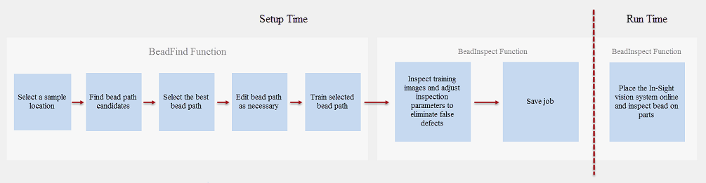
BeadFind Function
The BeadFind function consists of the following steps:
- Select a bead sample location
- Find bead path candidates
- Select the best bead path
-
Edit bead path (Optional)
If the found bead path is not ideal, modify the selected bead path as necessary.
- Train selected bead path
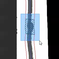
After inserting the BeadFind function into the spreadsheet, move the Bead Sample Location’s red circle graphic to a spot on the bead. Ensure the circle graphic covers both sides of the bead.
Click the Find Bead Paths button. The BeadFind function will start to find bead path candidates from the designated bead sample location automatically.
Once bead finding is completed, users can view the found bead path candidates and select the best bead path.
Click the Train Bead Path button to train the selected bead path.
BeadInspect Function
Once the sample bead is found and trained using the BeadFind function, the BeadInspect function is used to refine the bead analysis criteria and create measurement rules to identify bead defects during setup time. During run-time, bead paths will be compared to the trained model to determine if there are defects or gaps in the bead.
When refining the bead analysis criteria in the BeadInspect property sheet, users have two techniques for adjusting parameters to eliminate false defects, either by directly adjusting the parameters in the General tab or by accepting tool suggestions using the Fix button, next to each defect in the Defects tab.
For each bead inspection, the BeadInspect function will return the number of total defects and defect details will be listed in table format. By default the first 10 defects will be included in the table automatically. The table can be expanded to include more defects. In addition, users can use the other associated Vision Data Access functions to gather additional information to perform their own processing and analysis of the data generated by the BeadInspect function. For more information, see Bead.
Configure the BeadFind Function
-
Load a sample image to the job.
Tip:- BeadFind and BeadInspect functions work best with high contrast images with enhanced bead feature on a part.
- The sample image used to set up the BeadFind tool must contain a known good bead free of defects.
- Insert the BeadFind function into the Spreadsheet.
-
Select Bead Sample Location and click the Edit Graphic
 button.
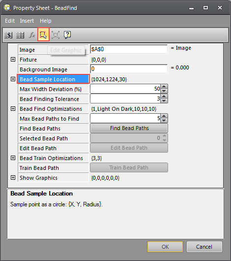 Tip:
Tip:- The bead sample location should be placed on a bead section that is representative of the entire bead.
- The bead sample location should be placed on a straight section of a bead free of noise.
- Do not select the bead sample location near holes or part edges.
- If a bead path is partially found, try adjusting the size of the sample circle or moving the bead sample location to where the bead path is not currently traced, then find the bead again.
-
If the width of a bead varies significantly, try selecting a section of the bead that has the medium width as the bead sample location.
-
In Interactive Graphics Mode, drag the red circle onto the bead to set up the bead sample location. For more information, see Interactive Graphics Mode.
The red circle should be placed onto a bead section that is representative of the entire bead and the red circle needs to enclose both edges of the bead. After the Bead Sample Location is set, click the Enter key or
 to go back to the property sheet.
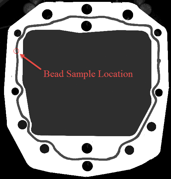
-
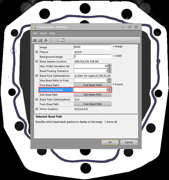
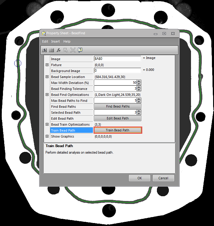
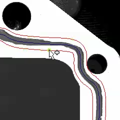
Click the Find Bead Paths button.
The found bead path candidates will be displayed in blue, and the number of bead paths found will be displayed to the right of the Find Bead Paths button.
Tip: If the bead is difficult to see, go to the Format > Format Cells... and adjust the Line width in the Graphics tab.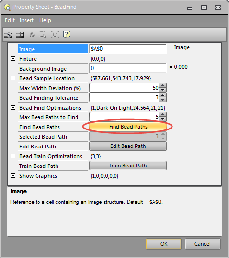
-
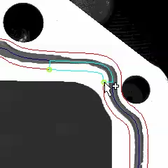
Review the bead path candidates by selecting numbers in the Selected Bead Path box.
In the following example, five bead path candidates are found and the number 3 bead path is the selected bead path.
-
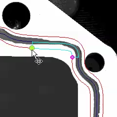
(Optional) If the selected bead path is not ideal, click the Edit Bead Path button to modify the bead path as necessary.
By placing the mouse cursor over various parts of the polyline, the mouse cursor will automatically transform, enabling the following actions:
Mouse Icon Description Right-click Context Menu 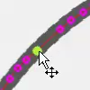
Select a point on the polyline. The selected point will be highlighted in green. The point can be moved by dragging the mouse cursor, or deleted via the delete key or the right-click context menu.
- Delete Point
- Open Polyline Here
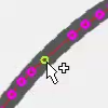
Place mouse cursor over the polyline path. The selected location will be highlighted in green. A point can be added by clicking the mouse or via the right-click context menu.
- Insert Point
- Open Polyline Here
Select multiple points by drawing a box over the points. The selected points will be highlighted in green. Once points are selected, they can be moved by dragging the mouse cursor, or deleted via the delete key or the right-click context menu.
- Delete Points
-
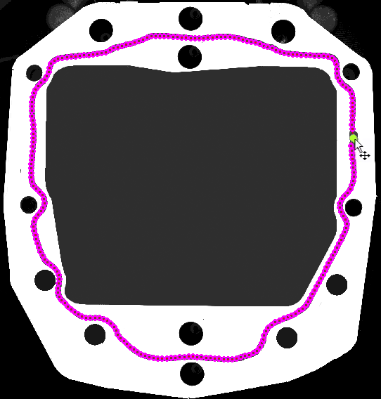
Once a bead path is selected and modified, click the Train Bead Path button to train the bead path. The trained bead path will be displayed in green.
- Click OK to exit the BeadFind tool.
Configure the BeadInsepct Function
- Insert the BeadInspect function into the Spreadsheet.
- Click on the BeadFind parameter in the Property Sheet. Press CTRL+SHIFT+A, or click the absolute reference
 button to set the BeadFind parameter as a cell reference to the previously created BeadFind data structure. Then click OK.
 -
When BeadInspect is inserted into a cell, a results table with 0 defect is created in the spreadsheet.
Note: Any trained bead is by definition a good bead. The initial parameters for the BeadInspect function therefore will be automatically set based on the referenced BeadFind function results to make sure no defects will be detected during the inspection of the trained bead path.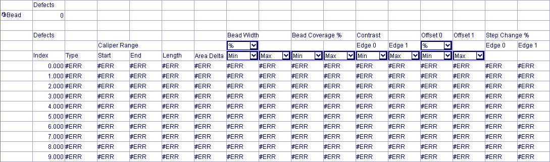
-
Load a training image to the job.
Once the image is loaded, the results table will get automatically updated with the latest inspection results.
-
Review Defects.
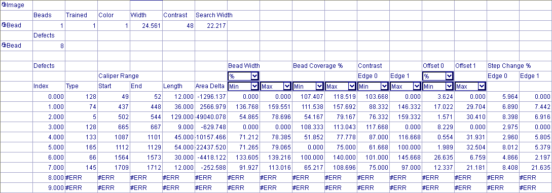
Open the BeadInspect Property Sheet and navigate to the Defects Tab to review defects. By default, the defect list is grouped by Defect Index.
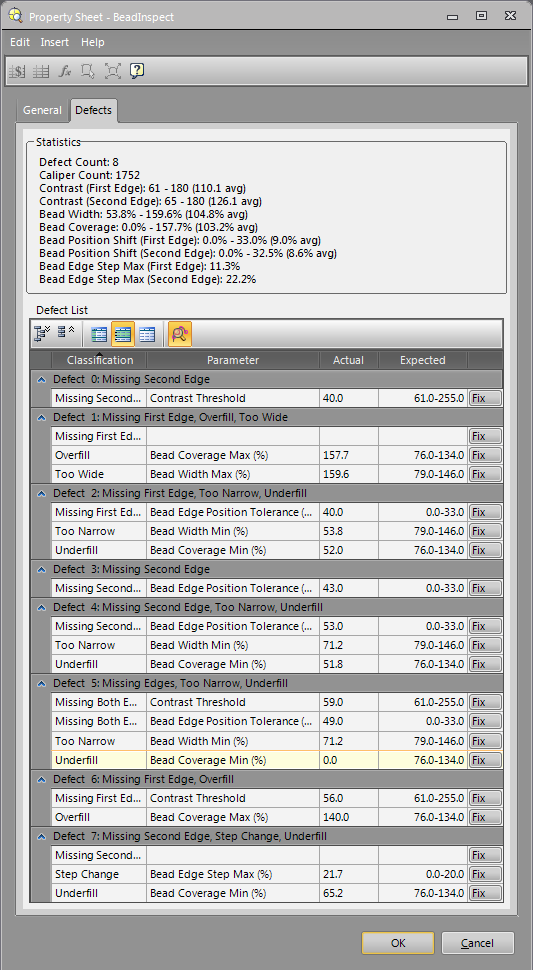
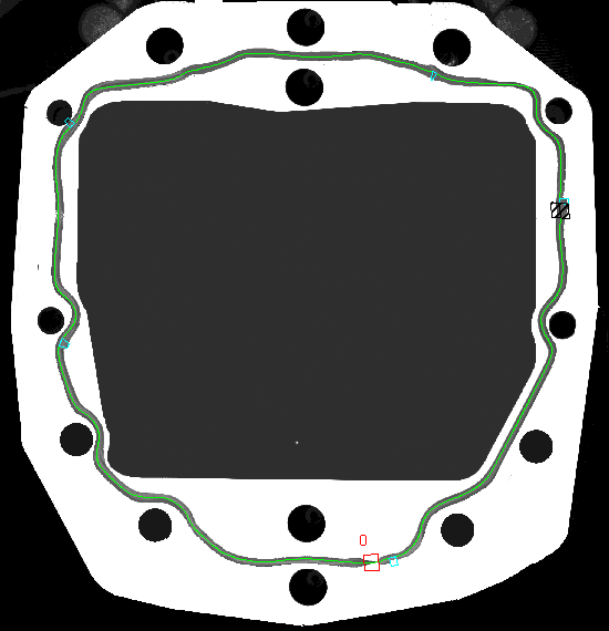
The following image illustrates an overview of eight bead defects found in the training image. The bead is defined as a bead with only one defect (Defect 5). All other detected defects are false defects which should be ignored during inspection. The BeadInspect parameters need to be adjusted during setup time to eliminate false defects so that the false defects will not be identified during future inspection.
Note: The bead example below is for demonstration purposes only.Defect Types and Related Parameters:
Defect Types Related Parameters Description Too Narrow
Bead Width Min (%)
Used to inspect the bead for sections that are too narrow. Too Wide
Bead Width Max (%) Used to inspect the bead for sections that are too wide. Underfill
Bead Coverage Min (%)
Used to inspect underfill defects where too little material is applied to a section of the bead. Overfill
Bead Coverage Max (%)
Used to inspect overfill defects where too much material is applied to a section of the bead. Step Change Bead Edge Step Max (%) Used to inspect protrusions or notches along the edges of the bead. Select a higher Bead Edge Step Max value to increase tolerance for beads with coarse or uneven edges. Use a lower bead step value for beads with smoother edges Missing First Edge
Missing Second Edge
Missing Both Edges
Contrast Threshold
Used to inspect missing edges defects. Bead edges with contrast values below the Contrast Threshold will be identified as defects. Bead Edge Position Tolerance (%) Used to inspect bead edges position changes. Bead edges that are outside of the Bead Edge Position Tolerance will not be found. 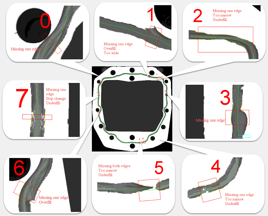
-
Adjust BeadInspect parameters to eliminate false defects.
The false defects can be automatically fixed using the Fix button in Defects Tab, or by manually adjusting the parameters associated with the defects in General Tab.
 Fix Missing Edge Defects Using the Allow Fill Edges Option
Note: The Allow Fill Edges option works only for Missing First Edge and Missing Second Edge defect types. It is not available if both edges are missing.
Fix Missing Edge Defects Using the Allow Fill Edges Option
Note: The Allow Fill Edges option works only for Missing First Edge and Missing Second Edge defect types. It is not available if both edges are missing.-
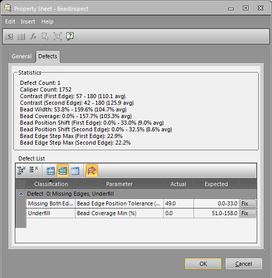
Select Defect 0 from the defect list. When a defect is selected, the image will be panned and zoomed to the location of the defect in the image.
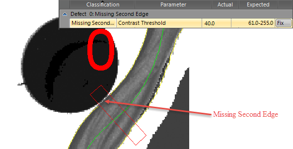
-
Click Fix button and choose Allow Fill Edges from the suggested menu.
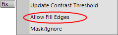
-
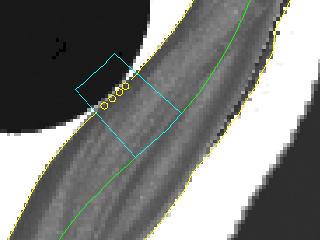
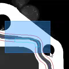
A cyan box will be drawn to indicate the fill edge region in the image.
- Once a defect is fixed, Defect 0 will be removed from the defect list table.
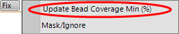
Fix Defects Using the Update Parameter Option
-
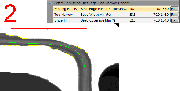
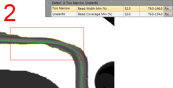
Select Defect 2 from the defect list.
Three types of defects are reported at this section of the bead: Missing First Edge, Too Narrow and Underfill.
-
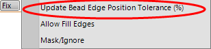
Click Fix button and choose Update Bead Edge Position Tolerance (%) from the suggested menu.
- The parameter associated with the Missing First Edge defect is Bead Edge Position Tolerance (%). The actual reported value is 40, which is above the specified Bead Edge Position Tolerance (%) value 33 listed in the General Tab.
- This defect can be fixed by updating the Bead Edge Position Tolerance (%) value from 33 to 40.
-
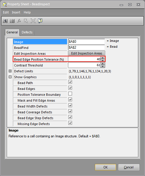
Once the Fix button is pressed, the Bead Edge Position Tolerance (%) value will be automatically updated to 40 so that the edge will be detected.
- Once this defect type is fixed, it will be removed from the Defect 2 list.
-
Select the next defect in Defect 2 list.
-
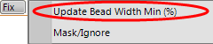
Click Fix button and choose Update Bead Width Min (%) from the suggested menu.
- The parameter associated with the Missing First Edge defect is Bead Width Min (%). The actual reported value is 52.3, which is below the specified Bead Width Min (%) value 79 listed in the General Tab.
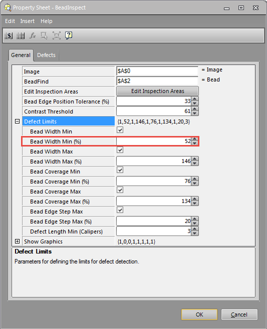
- This defect can be fixed by lowering the Bead Width Min (%) value from 79 to 52.
-
Once the Fix button is pressed, the Bead Width Min (%) value in the General Tab will be automatically updated so that the same edge section will not be identified as defects.
-
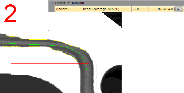
Select the last defect left in the Defect 2 list.
-
Click Fix button and choose Update Bead Coverage Min (%) from the suggested menu.
- The parameter associated with the Missing First Edge defect is Bead Coverage Min (%). The actual reported value is 52, which is below the specified Bead Coverage Min (%) value 76 listed in the General Tab.
- This defect can be fixed by lowering the Bead Width Min (%) value from 76 to 52.
- Once the Fix button is pressed, the Bead Coverage Min (%) value in the General Tab will be automatically updated so that the same edge section will not be identified as defects.
- Once all defect types in Defect 2 list are fixed, Defect 2 will be removed from the defect list table.
Fix a Group of Defects by Defect Types
Instead of fixing each defect individually, users can also fix a group of defects by defect types.
-
Open the BeadInspect Property Sheet and navigate to the Defects Tab. Click the
 button to group defect list by Defect Type.
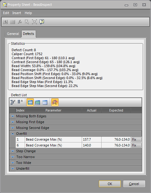
In this example, defect 1 and 6 are reported with the same defect type and the related parameter is Bead Coverage Max (%). The expected Bead Coverage Max (%) value is 134, while the actual reported Bead Coverage Max (%) value for Defect 1 and Defect 6 are 157.7 and 140.
-
To fix both defects, go to the General Tab, and update the Bead Coverage Max (%) value to 158.
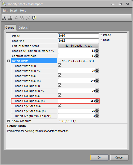
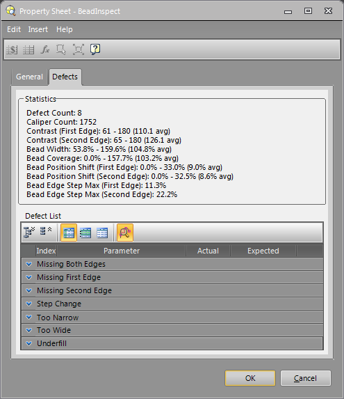
-
Once the value has been updated, the entire overfill defect type will be removed from the defect list table.
Use the Edit Inspection Areas
When the Train Bead Path is executed in the BeadFind function, the mask or fill edges areas will be automatically calculated and added to the bead inspection image.
To edit the preset inspection areas or add new inspection areas that can be masked out from inspection or allow fill edges, click The Edit Inspection Areas button in the general tab.
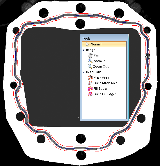
To add a mask area:
Note: The mask area should be used with caution. If an area is masked, it will be ignored in future inspections and defects in masked areas will not be reported.- Choose the Mask Area from the menu.
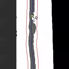
-
Select a position on the bead path where you want to create mask area.
-
Drag the point to create a mask area.
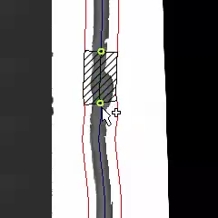
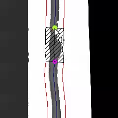
-
Move either point to adjust the mask area as necessary.
To erase a mask area:
- Choose the Erase Mask Area from the menu.
-
Select the mask area to be erased.
- The mask in selected area will be deleted.
To add a fill edges area:
Note: The Fill Edges Area option works only for Missing First Edge and Missing Second Edge defect types. This option is not available if both edges are missing.- Choose the Fill Edges from the menu.
-
Select a position on one of the bead edges (red polyline) where you want to create a fill edge area.
-
Drag the point to create a fill edge area.
-
Move either point to adjust the fill edge area as necessary.
To erase a fill edges area:
- Choose the Erase Fill Edge from the menu.
-
Select the fill edge area to be erased.
- The filled edge in selected area will be deleted.
-
-
Once all false defects are eliminated, there will be only one defect listed in the defect list table in this example.
- Click OK to exit the BeadInspect spreadsheet.
- Load the next image and repeat steps 5 to 8 until all the necessary bead instances have been trained.
- Save the job.
Refine Inspection Settings
The best way to achieve optimal bead inspection performance is to use a large number of images of real parts, including parts with both good and bad beads. The images of the beads should be representative of all possible bead instances that could occur during run-time. This will help you refine the inspection settings, including the use of fill edge and/or mask areas as appropriate.
Performance Verification
It is important to verify that the BeadInspect function works as expected after setting up the BeadFind and BeadInspect functions. It is recommended to rerun the BeadInspect function with all previous images and a new set of images to make sure that all defects are correctly identified and no false defects are reported.
Run the BeadFind and BeadInspect Functions
During run-time, the In-Sight vision system will be placed Online and acquire images as defined by the job. When an image is acquired, the bead is automatically detected and compared against the trained bead model. The results will be output via the Vision Data Access functions, and the BeadInspect Defects tab will provide additional information about the bead defects.