BeadFind
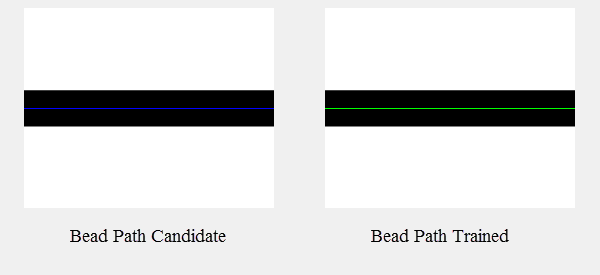
The BeadFind function is used to find the center of a bead feature, and create a polyline that traces the path of the detected bead. The bead path found and trained by the tool is used as an input by a BeadInspect function to determine positional, width, or coverage defects in the bead.
- BeadFind and BeadInspect functions are only available on In-Sight vision systems running In-Sight firmware 5.5.0 and later. For a complete list of models and supported firmware versions, see Firmware Versions. For more information on BeadInspect, see BeadInspect.
- BeadFind and BeadInspect functions do not support color images. If a color image is loaded, it will be automatically converted to a greyscale image.
-
For more information about how to use the BeadFind and BeadInspect functions, see Use the BeadFind and BeadInspect Functions.
BeadFind Inputs
Syntax: BeadFind(Image,Fixture,Background Image,Bead Sample Location,Max Width Deviation (%),Bead Finding Tolerance,Bead Find Optimizations,Max Bead Paths to Find,Find Bead Paths,Selected Bead Path,Edit Bead Path,Bead Train Optimizations,Train Bead Path,Show Graphics)
| Parameter | Description | ||||||||||||
|---|---|---|---|---|---|---|---|---|---|---|---|---|---|
|
Specifies a reference to a spreadsheet cell that contains an Image data structure; by default, this parameter references A0, the cell containing the AcquireImage Image data structure. This parameter can also reference other Image data structures, such as those returned by the Vision Tool Image functions or Coordinate Transforms Functions. |
|||||||||||||
|
Specifies the image coordinate system in which the bead path is defined. The default setting is (0,0,0), the top leftmost corner of the image.
|
|||||||||||||
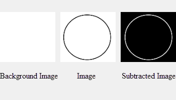
| Background Image |
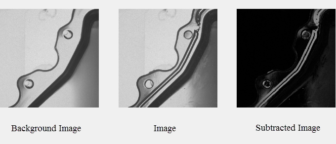
(Optional) Specifies a reference to a spreadsheet cell that contains an Image data structure of an image to be used for image subtraction. A background image should be an image without any bead material. It is used to create a high contrast image between an image with and without bead material to enhance the bead material visibility on a part during the bead find analysis. Note:
|
||||||||||||
| Bead Sample Location |
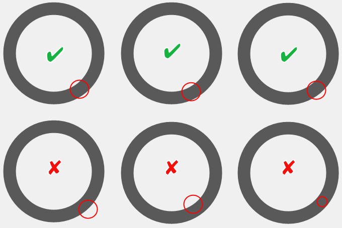
Specifies where the BeadFind function will begin to search bead path(s). The circle doesn't need to be placed in the center of a bead path, as long as the radius of the circle encloses both edges of the bead. Note: The value of the Radius parameter determines the width of the search calipers. If a section of the bead is wider than the search calipers, the bead search will fail.
|
||||||||||||
| Max Width Deviation (%) |
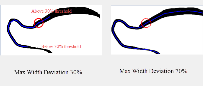
Specifies the maximum allowable bead width change in percentage (1-100; default = 50). The bead search stops if the bead width deviation is above or below the threshold. In this example, the Max Width Deviation is set to 30. The bead search stops when the bead width deviation is above the threshold at the top and below the threshold at the bottom. Adjust the Max Width Deviation value to 70, the entire bead path is traced.
|
||||||||||||
| Bead Finding Tolerance |
Specifies how aggressively to search for edges that comprise a bead (0-10; default = 3). A higher value allows bead finding to operate in areas of the image where the bead path is ambiguous. 0 = Least aggressive ... 10 = Most aggressive |
||||||||||||
| Bead Find Optimizations |
Specifies bead finding parameters that can be set manually or allowed to be automatically calculated by the tool.
|
||||||||||||
| Max Bead Paths to Find | Specifies the maximum number of possible bead path candidates to find (1 - 5; default = 5). The function will stop processing once the specified number of bead candidates are found. | ||||||||||||
| Find Bead Paths |
Click this button to start finding bead path candidates. The number of bead paths found will be displayed to the right of the button once the operation is completed. If no bead paths are found, 0 will be displayed. Note: Pressing the Find Bead Paths button will clear all previous bead path information including modifications to the existing paths or trained bead path data. To restore the information, press Cancel button to exit property sheet without saving any changes in the property sheet.
|
||||||||||||
| Selected Bead Path |
Specifies which of the possible bead path candidates will be used to display and to train the bead (0 to 4; default = 0). |
||||||||||||
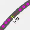
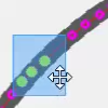
| Edit Bead Path |
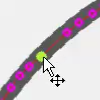
Click this button to switch to the Interactive Graphics Mode to manually adjust and optimize the points of the selected bead path before training. For more information on Interactive Graphics Mode, see Interactive Graphics Mode. Note:
By placing the mouse cursor over various parts of the polyline, the mouse cursor will automatically transform, enabling the following actions:
|
||||||||||||
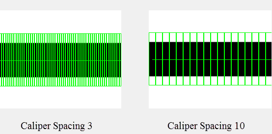
| Bead Train Optimizations |
Specifies training parameters for optimizing bead training.
|
||||||||||||
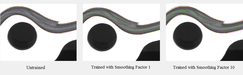
| Train Bead Path |
Click this button to train bead path. During training, detailed analysis of the bead characteristics are calculated. These calculations will be used to set initial values for a BeadInspect function that references this BeadFind tool. Note: If the BeadFind tool is retrained, a referencing BeadInspect will be modified with updated bead characteristics.
|
||||||||||||
| Show Graphics |
Specifies which BeadFind graphical overlays will be drawn on top of the image. |
BeadFind Outputs
|
Returns |
A Bead data structure containing the information about detected beads in the image, or #ERR if any of the input parameters are invalid. |
|
Results |
When BeadFind is initially inserted into a cell, a results table is created in the spreadsheet. For example, this is the default BeadFind results table:
|
