Communicate with a Mitsubishi Automation Controller on a CC-Link Network via an Anybus X-gateway
Overview
An In-Sight vision system can communicate with devices on a CC-Link network using an Anybus X-gateway and TCP/IP Modbus protocol. For more information, see Anybus X-gateway.
This topic explains how to install and configure the gateway, how to configure the Automation Controller programming software (Mitsubishi GX Developer), and how to set up In-Sight Explorer to communicate with a Mitsubishi Automation Controller on a CC-Link network.
The examples in this topic were written assuming that you are using the following components:
- Anybus X-gateway and HMS Anybus IPconfig software
- In-Sight vision system running firmware version 3.41.00 or higher
- A Mitsubishi Automation Controller that supports CC-Link
- Mitsubishi GX Developer programming software
Install and Configure an Anybus X-gateway
The steps contained in this section explain how to install and configure the Ethernet portion of the Anybus X-gateway. The procedure assumes that you are using the following components:
To install and configure an Anybus X-gateway:
- Download and install the HMS Software utility Anybus IPconfig; this utility uses the HMS IP Configuration Protocol (HICP), which provides a simple way to configure Anybus based Ethernet interfaces.
- Using a PC with Ethernet connectivity, run the Anybus IPconfig. A window will display all Anybus-based Ethernet interfaces, and their IP addresses, discovered on the network.
- Using the CC-Link station address switches on the Anybus X-gateway, set the CC-Link station address. Please refer to the X-gateway Interface Addendum - CC-Link Slave Interface for more information.
- Set the baud rate switch on the Anybus X-gateway to match the baud rate of the Automation Controller that you intend to communicate with.
- Physically mount and connect the Anybus X-gateway hardware; please refer to the Anybus X-gateway manual for more information.
- After the Anybus X-gateway hardware has been properly mounted and all cable connections have been made, provide power to the Anybus X-gateway hardware and wait 30 to 60 seconds for the device to power up. Once the Anybus-X Gateway hardware has power, the Ethernet LED status indicators should be either green or flashing green.
- From the Anybus IPconfig utility, click the Scan button to refresh the window that displays all Anybus-based Ethernet interfaces. The newly added Anybus X-gateway hardware should appear in the list, with a default IP address of 192.168.0.1.
- If the settings for the Anybus X-gateway need to be altered, double-click on the Anybus X-gateway in the list; this will display a dialog to assign IP addresses using DHCP or through a static IP address, subnet mask, default gateway and DNS server. Once the settings have been finalized, click on the Set button to continue.
- Finally, from the Anybus IPconfig utility, click the Scan button to refresh the window that displays all Anybus-based Ethernet interfaces. The Anybus X-gateway hardware should appear in the list, with the new IP address, if it was altered.
Connect an Anybus X-gateway to a Mitsubishi Automation Controller on a CC-Link Network
The Anybus X-gateway exchanges CC-Link data with the TCP/IP Modbus network and allows an In-Sight vision system's inputs and outputs to be sent to the processor’s memory in the Mitsubishi Automation Controller. Once these values are established, they are synchronized at an interval defined by the update rate of the CC-Link network.
Connect an Anybus X-gateway to an In-Sight Vision System via TCP/IP Modbus, describes how the actual data is transferred. Additionally, a snippet is included detailing a sample configuration.
In addition to the Anybus X-gateway, an Anybus Communicator can be used as a CC-Link master or slave. The following example uses an Anybus X-gateway.
Set Up CC-Link Communications
To setup a CC-Link connection between an Anybus X-gateway and a Mitsubishi controller, the Anybus X-gateway must first be configured to the same Baud rate as the Automation Controller and given a station number different from the controller. The switches can be found next to the power connector. See the Anybus user manual for further instructions. The next step is to configure the Automation Controller using the Mitsubishi GX Developer software.
-
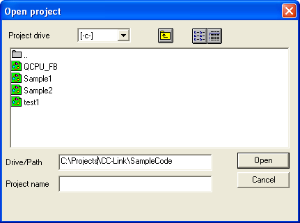
Open GX Developer, and load the Automation Controller's project.
-
Verify the Automation Controller Module setup. Double click on Parameter, then PLC Parameter and select the I/O Assignment tab.
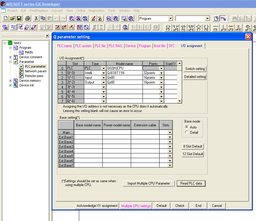
In this example we have one Q02(H), one Intelli, one Input and one Output device. For more information regarding the type and the number of points refer to the Mitsubishi manual.
-
Configure the CC-Link network. Double-click Network Parameter under Parameter and choose CC-Link.
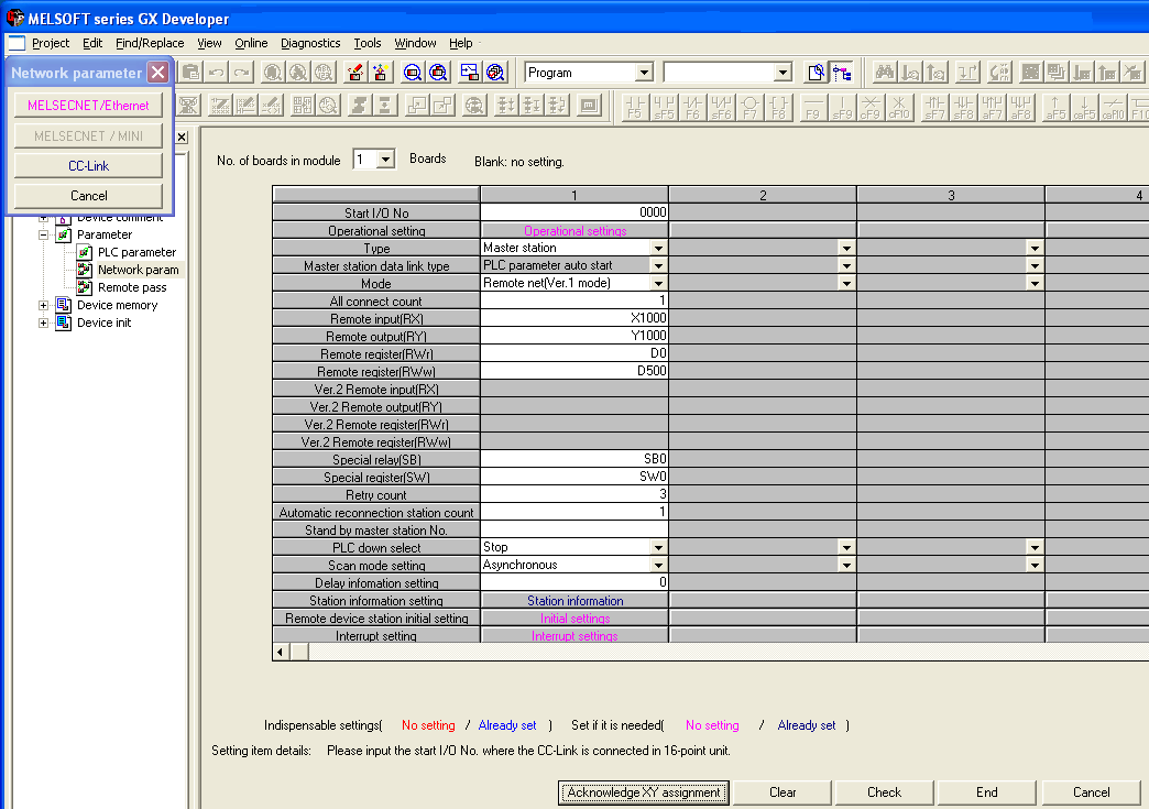
- The PLC is selected as the Master Station under Type.
- Remote net (Ver.1 mode) refers to CC-Link version 1.0 which is used with the Anybus X-gateway. Version 2.0 is selected when using the Anybus Communicator.
- Since our Anybus X-gateway is the only connected station All connect count is set to 1.
-
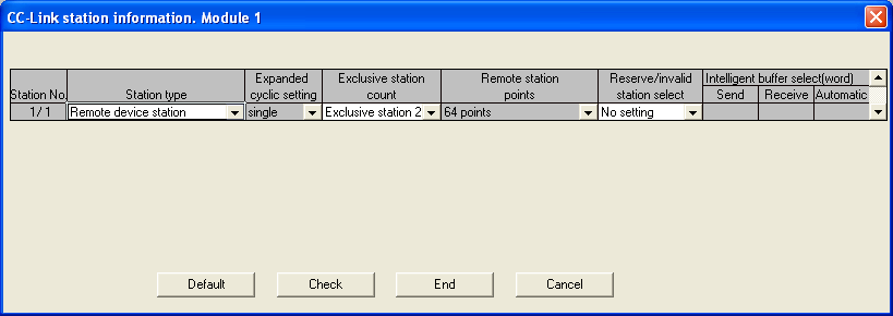
Configure the occupied stations. Double-click on Station information and the following screen appears.
Automation Controller Handshaking can now be configured. This is an optional procedure where the X-Gateway or Communicator requires a response from the Automation Controller. For more information see How to set up an Anybus Product with CC-Link and a Mitsubishi Automation Controller from the HMS website.
- Configure the X-Gateway to interact with the Automation Controller. Connect a serial cable between the PC and the config port of the Gateway and open Windows Hyperterminal (Start < Accessories < Communications< Hyperterminal).
- In the File Menu, click Properties.
-
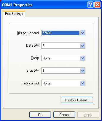
Click the Connect To tab, and select the appropriate COM port in the Connect using field, and click Configure. Use the settings in the following image.
Connect and press ESC to see the menu options.
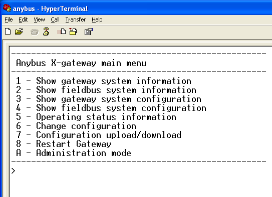
Press 6 and enter the configuration information below. It must match the information entered in the Automation Controller configuration screens.
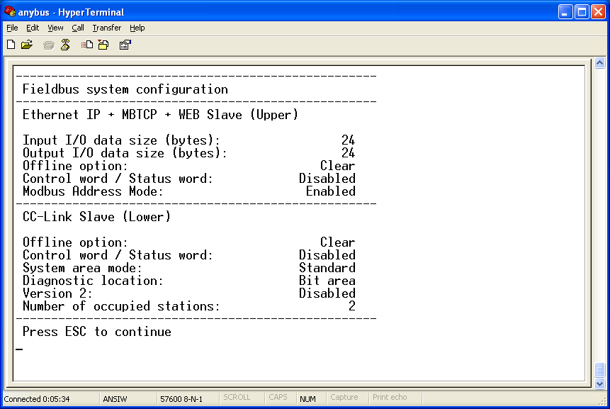
Reboot the device. The system is now fully configured.
Connect an Anybus X-gateway to an In-Sight Vision System via TCP/IP Modbus
This section describes connecting an Anybus X-gateway to an In-Sight vision system, using TCP/IP Modbus communications. For more information, see Modbus TCP Communications.
Set Up TCP/IP Modbus Communications in In-Sight Explorer
TCP/IP Modbus client functionality is enabled on In-Sight vision systems, but this server functionality is not needed in this model, because the Anybus X-gateway acts as the TCP/IP Modbus server (slave).
- In In-Sight Explorer, select the In-Sight vision system or emulator that is to be configured from the In-Sight Network pane.
- From the File menu, select New Job to load a new job on to a vision system or emulator.
- From the Palette, select the Snippets tab and expand the Communications folder. Load the CCLinkGateway.cxd file to cell A2 in the In-Sight Explorer spreadsheet by either first selecting A2 and double-clicking on the CCLinkGateway.cxd or drag-and-drop the file into cell A2.
- Save the new job to the vision system or emulator as CCLinkGateway.job.
- Double-click cell A5 and enter the IP Address of the Anybus X-gateway (if necessary, run the HMS Anybus IPconfig software utility to return the Anybus X-gateway's IP address).
- TCP/IP Modbus communications require that an In-Sight client (master) has the following functions present in the job: TCPDevice and QueryDevice. The TCPDevice function is used to create the network connection between the remote device, in this case, the Anybus X-gateway, and an In-Sight vision system. The QueryDevice function is used to construct the Modbus Function Code command of the TCP/IP Modbus packet. The CCLinkGateway.cxd file contains a TCPDevice function at cell C5, and two QueryDevice functions: one in cell B15 for Read requests, and the other in cell B28, for Write requests. For more information, see TCPDevice and QueryDevice.
-
The Anybus X-gateway supports the following Modbus Function Codes in the QueryDevice function:
Function Code Function Name 3
Read multiple registers
4
Read input registers
6
Write single register
7
Read exception status
8
Diagnostics
16
Force multiple registers
22
Mask write register
23
Read/Write registers
-
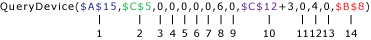
Double-click the QueryDevice function, located in cell B15, and ensure that it has the following parameter settings:
 Note: Please refer to the Modbus Implementation Guide for more information on the Modbus packet structure.
Parameter Input Number Parameter Input Name Parameter Input Value Description 1
Event
$A$15
A cell reference to an Event button. For more information, see Event.
2
Device
$C$5
A cell reference to the TCPDevice function in cell C5.
3
Data
0
Modbus header, Transaction Identifier, upper byte = 0.
4
Data
0
Modbus header, Transaction Identifier, lower byte = 0.
5
Data
0
Modbus header, Protocol Identifier, upper byte = 0.
6
Data
0
Modbus header, Protocol Identifier, lower byte = 0.
7
Data
0
Field Length, upper byte = 0.
8
Data
6
Field Length, lower byte = 6 (bytes to follow).
9
Data
0
Unit ID, byte not used = 0.
10
Data
$C$12+3
Modbus Function Code byte; in this example, this input will equal 3 or 4.
Note: When the Modbus Function Code byte is set to 3, In-Sight reads the holding registers (the data written via TCP/IP Modbus); when the Modbus Function Code byte is set to 4, In-Sight reads the input registers (data written via CC-Link)11
Data
0
Modbus reference address, upper byte = 0.
Note: Input registers may be read using Read multiple registers (Function Code 3) from address 1000, or using Read input registers (Function Code 4) from address 0.12
Data
$E$19
Modbus reference address, lower byte = 4. The first 4 bytes are used to specify the “Bit Area” size. In this case the first 4 bytes cannot be used for data exchange and are reserved due to the number of occupied stations.
Note: Input registers may be read using Read multiple registers (Function Code 3) from address 1000, or using Read input registers (Function Code 4) from address 0.Note: For more information see Data Exchange basics (chapter 2-1) in the X-gateway Interface Addendum - CC-Link Slave Interface available on the support page of the HMS website (hms-networks.com).13
Data
0
Word (register) count, upper byte = 0.
14
Data
$B$8
Word (register) count, lower byte.
In this example, this input will equal 1, 2, 3, 4, 6 or 8.” .
-
The TCP/IP Modbus response packet from the Anybus X-gateway is stored in the binary structure of the QueryDevice function; these return values are read in In-Sight Explorer by the BGetInt function. For more information, see Binary Text Functions. This function returns integer values from a specific byte from a binary structure, and the response is formatted as follows:
Byte Number Modbus Response Description Byte 7
Modbus Function Code
In this example, 3 or 4. If the command fails, 128 is added to the Function Code (the value returned would then be 131 or 132, see cell E15).
Byte 8
Byte Count
In this example, 2 registers (words) = 4 bytes. See cell E15.
Byte 9/10
Value in Register 0
These values are in the two-byte format. In the CCLinkGateway.cxd file, the BGetInt function in cell D18 reads the binary value at Byte 9 (the lower byte of the word read).
Byte 11/12
Value in Register 1
These values are in the two-byte format. In the CCLinkGateway.cxd file, the BGetInt function in cell D19 reads the binary value at Byte 11 (the lower byte of the word read).
Byte 13/14
Value in Register 2
These values are in the two-byte format. In the CCLinkGateway.cxd file, the BGetInt function in cell D20 reads the binary value at Byte 13 (the lower byte of the word read).
Byte 15/16
Value in Register 3
These values are in the two-byte format. In the CCLinkGateway.cxd file, the BGetInt function in cell D21 reads the binary value at Byte 15 (the lower byte of the word read).
Byte 17/18/19/20
Value in Registers 3 and 4 that store a floating-point number
These values are in the floating-point format. In the CCLinkGateway.cxd file, the BGetInt function in cell D22 reads the binary value at Byte 17 (the lower byte of the word read).
Byte 21/22/23/24
Value in Registers 5, 6 and 7 that store a string (in byte array)
These values are in the string format. In the CCLinkGateway.cxd file, the BGetInt function in cell D23 reads the binary value at Byte 21 (the lower byte of the word read).
- The QueryDevice function, in cell B28, for the Write request, is formatted in the same manner as the Request and Response packets.
Read Data to an In-Sight Vision System from a Automation Controller Via CC-Link
Following the example provided by this model, the Input Buffer of the Anybus X-gateway is the data source being read; this buffer holds the data requested by the In-Sight vision system (on the TCP/IP Modbus network) from the Automation Controller (on the CC-Link network).
- Continue using the In-Sight Explorer job created in the Set Up TCP/IP Modbus Communications in In-Sight Explorer section.
- Open CC-Link Configurator (GX Configurator-CC). If necessary, download the project to the Mitsubishi Automation Controller using GX Developer. In addition, GX Developer may be used for more complex data manipulation.
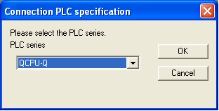
-
Select QCPU-Q as the Automation Controller series.
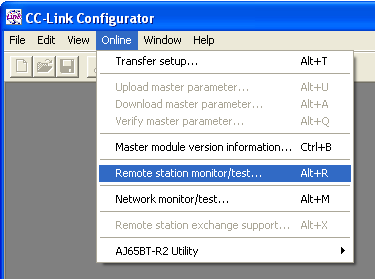
-
From the Online menu, select Remote station monitor/test.
-
Configure the Remote station monitor/test dialog as shown below.
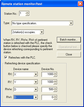
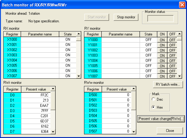
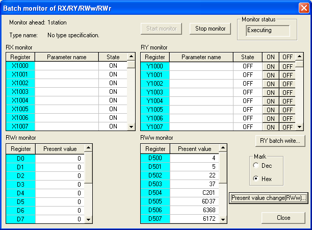
- Click on Batch monitor, then on Start monitor.
-
Enter hexadecimal or decimal equivalent of the values to be read by clicking Present value change(RWw). Note that the values are displayed in big endian notation even though they are being transferred by In-Sight Explorer in little endian notation.
- In cell A8 of the CCLinkGateway.cxd file, select 8 for the number of registers (16 bytes).
-
In cell C12, select Input Registers from the drop-down list for the Read Registers.
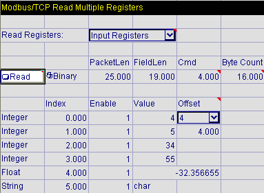
- Click on the Read Button in cell A15 to update the results. The values in cells D18-D23 should change to reflect the values that were entered in the CC-Link Configurator. For more information, see Button.
Write Data From an In-Sight vision system To a Automation Controller Via CC-Link
Following the example provided by this model, the Output Buffer of the Anybus X-gateway is the data source being written to; this buffer holds the data written by the In-Sight vision system (on the TCP/IP Modbus network) to the Automation Controller (on the CC-Linknetwork).
- In cell A8 of the CCLinkGateway.cxd file, select 8 for the number of registers (16 bytes).
- In cell C12, select Holding Registers from the drop-down list for the Read Registers; this will read data from the same registers that are being written from within the In-Sight job.
-
Next, adjust the values in cells D31-D36 so that they are valid data types for the application. Enter values into the EditInt cells for the four integers in cells D31-D34 (the minimum value is -32768 and the maximum is 32767, so the value must be a valid integer between that range); the floating-point value in cell D35 (the minimum value is ±1.175495e-38 and the maximum value is ±3.402823e+38, so the value must be a valid floating-point value between that range); and the 4 byte string in cell D36 (the string can be no longer than 4 characters/bytes). For more information, see EditInt.
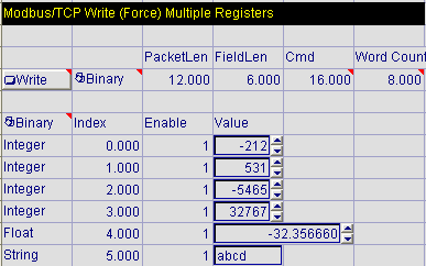
-
Click the Write Button in cell A28 to write the results from the In-Sight Explorer spreadsheet to the Automation Controller.
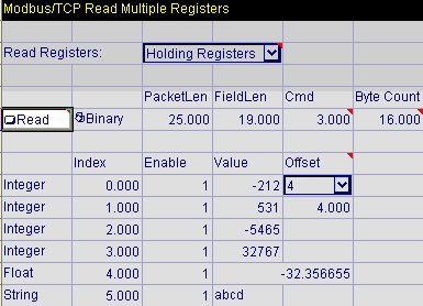
- Click the Read Button in cell A15; the values in cells D18-D23 should change to reflect the values that were entered in cells D31-36.
- Open CC-Link Configurator (GX Configurator-CC). If necessary, download the project to the Mitsubishi Automation Controller using GX Developer. In addition, GX Developer may be used for more complex data manipulation.
-
Select QCPU-Q as the Automation Controller series.
-
From the Online menu, select Remote station monitor/test.
-
Configure the Remote station monitor/test dialog as shown below.
-
Click on Batch monitor, then on Start monitor. The values under RWr monitor should change to reflect hexadecimal or decimal equivalent of the values that were entered in the In-Sight Explorer spreadsheet. Note that the values are displayed in big endian notation even though they are being transferred by In-Sight Explorer in little endian notation.