Communicate with a Mitsubishi Automation Controller on a CC-Link Network via an In-Sight CIO-MICRO-CC I/O Module
This topic encompasses an overview of the Mitsubishi CC-Link communication protocol and how to incorporate In-Sight vision systems with Mitsubishi Q-Series Automation Controllers, using the In-Sight CIO-MICRO-CC I/O module. Connected directly to the Automation Controller through a CC-Link specified cable, the CIO-MICRO-CC I/O module and the vision system are capable of being used in either an Endpoint or Midspan configuration for CC-Link communications. For more information about the connection and installation of the devices, please refer to the In-Sight® CIO-MICRO and CIO-MICRO-CC I/O Module Installation Manual included with In-Sight Explorer software.
Configure In-Sight Vision Systems for CC-Link Protocol Communications
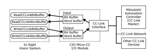
This section describes how to connect to an In-Sight vision system using CC-Link communications to a Mitsubishi Q-Series Automation Controller. The CIO-MICRO-CC I/O Module acts as a gateway between the In-Sight vision system and the Mitsubishi Q-Series Automation Controller. The ReadCCLinkBitBuffer, ReadCCLinkWordBuffer, WriteCCLinkBitBuffer and WriteCCLinkWordBuffer functions are used to create a CC-Link protocol connection between an In-Sight vision system and a Mitsubishi Automation Controller. For more information, see ReadCCLinkBitBuffer, ReadCCLinkWordBuffer, WriteCCLinkBitBuffer, or WriteCCLinkWordBuffer.
Configure the In-Sight CIO-MICRO-CC for CC-Link Communications
CC-Link communications are set up through the CC-Link connection on the CIO-MICRO-CC I/O module and the Mitsubishi Q-Series Automation Controller. These steps assume that the In-Sight vision system and CIO-MICRO-CC I/O module have been connected to the Automation Controller, and are ready to be configured within In-Sight Explorer for CC-Link communications.
- From the In-Sight Network pane, select the desired In-Sight vision system and connect to it. For more information, see In-Sight Network.
- From the Sensor menu, select CC-Link Settings to launch the CC-Link Settings dialog.
- If the desired CIO-MICRO-CC I/O module is not displayed in the CC-Link Settings dialog, press the I/O Module button, which opens the I/O Module Configuration dialog, to configure the I/O module.
- In the CC-Link Settings dialog, configure the settings to match those of the connected Mitsubishi Q-Series Automation Controller.
- Press OK to close the CC-Link Settings dialog.
Get Data From an In-Sight Vision System to a Mitsubishi Automation Controller
In order to get data from the In-Sight Explorer spreadsheet to a Mitsubishi Automation Controller, the data must be transferred using the WriteCCLinkBitBuffer (e.g. pass/fail data) and WriteCCLinkWordBuffer (e.g. integer, floating-point values and string data) functions. Each function takes an individual buffer of data created by a FormatOutputBuffer function and writes the data to the CC-Link memory buffers on the CIO-MICRO-CC I/O module. This data is then transferred during the next update cycle. For more information, see FormatOutputBuffer.
- Right-click an empty cell and select Insert Function to open the Insert Function dialog. From the left pane, click on the Input/Output category, then double-click the FormatOutputBuffer function, from the right pane, to insert it into the spreadsheet.
- This FormatOutputBuffer function will be used to transmit the word data (e.g. integer, floating-point values and string data).
- From the FormatOutputBuffer dialog, click on the Add button. This will initiate the cell selection mode; select the integer, floating-point values and/or string data that will be transferred to the Mitsubishi Automation Controller. For more information, see Cell Selection Mode.
- If there is additional data to be sent, again, from the FormatOutputBuffer dialog, click on the Add button. Once again this will initiate the cell selection mode; select the additional data to transfer.
- Close the FormatOutputBuffer dialog by clicking the OK button.
- Right-click an empty cell and select Insert Function to open the Insert Function dialog. From the left pane, click on the Input/Output category, then double-click the WriteCCLinkWordBuffer function, from the right pane, to insert it into the spreadsheet.
- Set the WriteCCLinkWordBuffer function's Buffer parameter as a cell reference to the recently created FormatOutputBuffer function's Buffer data structure. For more information, see Cell References - Relative/Absolute.
- Add another FormatOutputBuffer function; this function will be used to transmit the bit data (e.g. pass/fail data).
- Follow the directions for step 3. When configuring the FormatOutputBuffer function, ensure that the Data Type parameter is set to Bit.
- Close the FormatOutputBuffer by clicking the OK button.
- Add the WriteCCLinkBitBuffer function to the spreadsheet.
- Set the WriteCCLinkBitBuffer function's Buffer parameter as a cell reference to the recently created FormatOutputBuffer function's Buffer data structure.
Send Data to an In-Sight Vision System From a Mitsubishi Automation Controller
In order to send data from the Mitsubishi Automation Controller to the In-Sight Explorer spreadsheet, the data must be transferred from the CIO-MICRO-CC I/O module by using the ReadCCLinkBitBuffer (e.g. enabling/disabling functions) and ReadCCLinkWordBuffer (e.g. integer, floating-point values and string data) functions. These functions take the formatted data created within the FormatInputBuffer function and reads the corresponding memory area of the CIO-MICRO-CC I/O module. This data is then formatted into the In-Sight Explorer spreadsheet. For more information, see FormatInputBuffer.
- Right-click an empty cell and select Insert Function to open the Insert Function dialog. From the left pane, click on the Input/Output category, then double-click the FormatInputBuffer function, from the right pane, to insert it into the spreadsheet.
- This FormatInputBuffer function will be used to receive the word data (e.g. integer, floating-point values and string data).
- From the FormatInputBuffer dialog, click on the Add button and add a 32-bit float and a 32-bit integer to the list.
- Close the FormatInputBuffer dialog by clicking the OK button.
- Right-click an empty cell and select Insert Function to open the Insert Function dialog. From the left pane, click on the Input/Output category, then double-click the ReadCCLinkWordBuffer function, from the right pane, to insert it into the spreadsheet .
- Set the ReadCCLinkWordBuffer function's Buffer parameter as a cell reference to the recently created FormatInputBuffer function's Buffer data structure.
- Add another FormatInputBuffer function; this function will be used to receive the bit data (e.g. enabling/disabling functions).
- From the FormatInputBuffer dialog, click on the Add button and add a bit data type.
- Close the FormatInputBuffer dialog by clicking the OK button.
- Add the ReadCCLinkBitBuffer function to the spreadsheet.
- Set the ReadCCLinkBitBuffer function's Buffer parameter as a cell reference to the recently created FormatInputBuffer function's Buffer data structure.
- Once the functions have been implemented, place the In-Sight vision system Online to test the configuration. For more information, see Online/Offline.