Caliper
Used to perform the following edge-related inspections: measure the width of objects, determine the location of single edges and the location and spacing of edge pairs. The Caliper function is the most accurate Edge function, however, it requires more time to setup and configure.
Caliper Overview
The Caliper function is used to examine an image and locate a 1-dimensional edge, a change in the greyscale values of neighboring pixels. The function examines a specified portion of the image (defined by the Region parameter) and scans for a transition in the greyscale values of pixels along one direction, from dark to light or light to dark. Either a single edge or a pair of edges (that are separated by an expected width) can be located by the function.
The Caliper function is ideally suited to applications where the function is used to develop detailed information about the precise locations of edge features within or around an object. For example, the function could be used to count leads on a chip, measure the width of a part, or find edge points to be used as an input for another Vision Tool. The function locates edges or edge pairs based upon an edge model, in which potential edge candidate peaks are detected using a simple 1D kernel, and then scored against a model and scoring methods.
Once the location and orientation of the edges of interest within the image have been determined, the Caliper function can be applied:
- Configure the Region to enclose the edges or edge pairs.
- Set the Edge Mode parameter to the type of edge (single edge or edge pairs) and specify the number of edges to find, and set the Edge: First, Edge: Second, and Edge: Distance parameters to create an edge model, which includes the edge polarity, position and spacing.
- Set the Edge Width and Minimum Contrast parameters to isolate the edges or edge pairs.
- Define the scoring method that will be used to score edge candidates.
Configuring the Region
When positioning the region, ensure that the scan direction is set to properly identify the desired edges. The scan direction should be pointing towards the first edge to be detected. Edge position will be determined by where the edges are detected, relative to the center of the region.
Isolating Edges and Defining the Edge Model
Once the edges have been located in the region, the Caliper function computes a score for each potential edge in the image. The score for each edge is computed based on the similarity between the edge in the current image and the defined ideal edge. The edges in the current image are considered "edge candidates," while the ideal edge is called the "edge model" (which can be a single edge or a pair of edges).
Edge Model
To evaluate whether an edge candidate in the image is a good match for the edge sought, a model that accurately describes the edge of interest must be defined. An edge model is defined by first defining the type of edge: a single edge or a pair of edges. Next, define how many of the edge types to locate in the region. Then specify the polarity (white-to-black or black-to-white), position of each edge in the model, which is specified by the position of the edges relative to the Region, and the spacing between edges if edge pairs are being defined.
Edge Detection, Peak Detection with the Minimum Contrast Threshold
The Edge Width parameter is used to remove noise from the input image, and accentuate the peaks of the edge profiles. Use the Minimum Contrast parameter to set a minimum peak height (contrast threshold).
Edge Mode Scoring
Once the Caliper function has filtered the region and produced a list of the edge peaks that exceed the specified contrast threshold, the function computes a score for each edge candidate within the image. This score determines which of the edge candidates in the image represent instances of the actual edges of interest, as defined by your edge model.
The Caliper function computes the score for each edge candidate by comparing the edge candidate against the edge model, based upon a set of user-defined scoring criteria, called scoring methods.
A scoring method has two parts:
- A scoring method type that defines what measurement of the edge you want to evaluate
- A scoring function that defines the relationship between the raw measure and the mapped score that will be generated for the scoring method
Several scoring methods can be defined; the Caliper function applies all of defined scoring methods to each edge candidate within the image and returns an overall score for each edge candidate. Defining the appropriate scoring methods ensures that the edge candidate with the highest score will be the edge of interest.
Scoring Method Types
The Caliper function bases the score of an edge candidate on how different the edge candidate is from the edge model. The particular measure that the tool uses to assess this difference is defined by the user. The types of measures that can be specified are called scoring method types, and there are four types of scoring methods: Contrast, Position, Size and Straddle.
When the function applies a scoring method type to an edge candidate, the result is a raw score. The raw score is different for different scoring method types. The scoring method types and their raw scores are described in the following sections.
Contrast Scoring Methods
Edge candidates can be scored based on the contrast of the edge candidates. The contrast of an edge is expressed in terms of the change in pixel values divided by the size of the edge, in pixels. The raw score for a contrast scoring method is normalized so that a value of 100 is equal to a contrast of 256 (the maximum possible value for contrast). If an edge pair model is specified, the raw score is the average of the contrast for the two edges.
Positional Scoring Methods
Edge candidates can be scored based on the position of the edge candidate relative to the center of the region. The position is defined as the distance between the center and the model origin point within the edge candidate. If the edge of interest is expected to be a specific distance from the center of the region, then an absolute positional scoring method can be defined, and the raw score will be expressed as an absolute distance in pixels. If an edge pair model is being used and the variation in position between the edge candidate and the center of the region relative to the size of the model should be accounted for, define a relative positional scoring method. In this case, the raw score will be normalized so that a value of 100 means that the distance was equal to the size of the model.
Size Scoring Methods
If an edge pair model is being used, edge candidates can be scored based on how much the width between the edges of the edge candidate varies from the width between the edges of the edge model. The size scoring method can be defined to be absolute, in which case the raw score will be returned as an absolute size difference in pixels. If the size difference relative to the size of the model should be qualified, define a relative size scoring method. In this case, the raw score will be normalized so that a value of 100 means that the size difference was equal to the size of the model.
Straddle Scoring Methods
If an edge pair model is being used, edge pair candidates can be scored based on whether or not the two edges lie on either side of the center of the region. This type of scoring method can be used to find objects defined by a pair of edges that are expected to lie under the center of the region. The raw score is returned as 100 if the center of the region is straddled by the edges, 0 if the center of the region is not straddled by the edges.
Scoring Functions
For each scoring method, the selected scoring method type produces a raw score; the effect that this raw score has on the overall score for an edge candidate is controlled by defining a scoring function. A scoring function maps a raw score to a mapped score. The mapped scores for each scoring method for an edge candidate are combined to form the overall score for that edge candidate.
Caliper General Tab
| Parameter | Description | ||||||||||||
|
Image |
This parameter must reference a spreadsheet cell that contains an Image data structure; by default, this parameter references A0, the cell containing the AcquireImage data structure. This parameter can also reference other Image data structures, such as those returned by the Image Vision Data Access Functions or Coordinate Transforms Functions. |
||||||||||||
|
Fixture |
Defines the Region of Interest (ROI) relative to a Fixture input or the output of a Vision Tools function's image coordinate system. Setting the ROI relative to a Fixture ensures that if the Fixture is rotated or translated, the ROI will be rotated or translated in relation to the Fixture. The default setting is (0,0,0), the top leftmost corner of the image.
|
||||||||||||
|
Region |
Also known as the Region of Interest (ROI), specifies the region of the image that undergoes analysis. Double-click on the Region parameter to create an Interactive Graphics Mode that you can transform and rotate. Select this parameter and press the Maximize Region button on the Job Edit toolbar of the property sheet to automatically stretch the region to cover the entire image.
|
||||||||||||
|
Note: The Fixture and Region parameters must be defined
within the bounds of the image; otherwise, the function will return #ERR.
|
|||||||||||||
|
Edge Mode |
Specifies whether the function should locate a single edge or an edge pair.
|
||||||||||||
|
Number to Find |
Specifies the maximum number of edges or edge pairs to return (1 to the In-Sight camera's image width, minus 1; default = 1). The maximum number of edges that may be detected is one less than the width of the image for the particular In-Sight camera capturing the image (i.e., an ISC 8402 camera's maximum would be 1599, or one less than the vision system's 1600 x 1200 image resolution). If there are more edges or edge pairs whose scores exceed the Thresh: Accept parameter value, the edges or edge pairs with the highest scores will be selected. |
||||||||||||
|
Minimum Contrast |
Specifies the minimum contrast (0 to 100; default = 5) for edges or edge pairs; the contrast value is normalized from the greyscale histogram within the Region to a scale of 0 to 100. The function will only return edges or edge pairs with contrast values that exceed this setting. |
||||||||||||
|
Thresh: Accept |
Specifies the minimum acceptable match score (0 to 100; default = 5) for edge candidates; the function only returns those edges or edge pairs with match scores that exceed this value. The match score is the geometric means of all of the specified scoring methods. |
||||||||||||
|
Edge Width |
Specifies the pixel distance (1 to 50; default = 2) over which an edge transition takes place. Edge Width is used to filter the image before edges are extracted. |
||||||||||||
|
Edge: First |
Specifies the polarity of the first edge in a pair, relative to the scan direction in the Region; when set as either black-to-white or white-to-black, the function only reports edge pairs whose first edge has the specified polarity.
|
||||||||||||
|
Edge: Second |
Specifies the polarity of the second edge in a pair, relative to the scan direction in the Region; when set as either black-to-white or white-to-black, the function only reports edge pairs whose second edge has the specified polarity. Note: This parameter is used only when the Edge Mode parameter is set to Edge Pair.
|
||||||||||||
|
Edge: Distance |
Specifies the pixel distance (1 to 3 times the In-Sight vision system's width; default = 10) between the two edges in an edge pair. This parameter is used only for the Edge Pair mode. If the edge distance is greater than the Region width, the function will return #ERR. If the Region is not rotated or curved, this value needs to be less than or equal to Region > Wide. Note: The In-Sight vision system's image width is the width of the image for the particular In-Sight vision system capturing the image (i.e., an In-Sight 5100 vision system's maximum would be 1920, 3 times the width of the vision system's 640 x 480 image resolution).
|
||||||||||||
|
Show |
Specifies the display mode for Caliper graphical overlays on top of the image.
|
||||||||||||
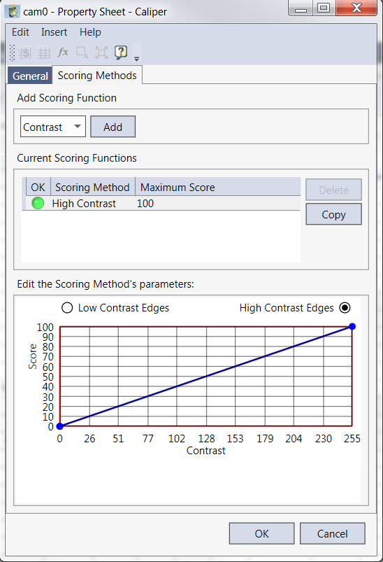
Caliper Scoring Methods Tab
The Scoring Methods tab is used to select and edit the scoring functions that will be used to score edge candidates against the edge model. For each edge candidate, once the Caliper function has computed the raw score for each selected scoring method and applied the scoring function, an overall score is then computed for the edge candidate. The overall score is computed by taking the Nth root of the product of the mapped scores. For example, if four scoring methods are defined, the Caliper function would multiply the four scores and take the 4th root of the result (if any single scoring function produces a value of 0, then the overall score for the edge candidate would be also be 0).
The Caliper Scoring Methods Tab is divided into three areas:
- Add Scoring Function
- Current Scoring Functions
- Editing the Scoring Method's Parameters
Scoring Functions
From the Add Scoring Function section, choose either Position, Contrast, Size or Straddle from the drop down menu. Click the Add button to commit.
| Parameter | Description |
|
Position |
Available for edge pairs and single edges, this scoring method is based on the edge's, or edge pair's, position relative to the left-side or center of the Region. Adjust the scoring settings to assign scores to edges or edge pairs based on their proximity to the left-side of the Region, with a score range of 0 to 100. When the Region Centered check-box is enabled (its default state), edges or edge pairs are scored based on their position relative to the center of the Region. Select either the Outside Edge or Centered Edges radio button as the basis for the scoring calculation. Centered edges are those closer to the center of the Region, while outside edges are those further away from the center. If the Region Centered check-box is not enabled, the scoring is based on the position relative to the left-side or right-side of the Region. Select either the Left Side Edges or Right Side Edges radio button as the basis for the scoring calculation. The Normalize to Edge Pair Distance check-box (which is only used for edge pairs), divides the distance between the edges in the edge pair by the Edge: Distance parameter value before calculating the score. This provides a way to accommodate size changes in the Region by using a percentage value, rather than an actual value, in calculating the score. Note: Normalize to Edge Pair Distance is available for Edge Pairs only.
|
|
Contrast |
Available for edge pairs and single edges, this scoring method is based on the edge candidate's contrast, which is the change in contrast across adjacent pixels that make up the edge. With edge pairs, the average contrast of the two edges is used. Adjust the scoring settings to assign scores to edges or edge pairs based on the contrast, with a score range of 0 to 100. The basis for calculating the score can be either Low Contrast Edges or High Contrast Edges. |
|
Size |
Note: Available for Edge Pairs only.
This scoring method is based on the distance (size) between edge pairs. Adjust the scoring settings to assign scores to edge pairs based on their size, with a score range of 0 to 100.
The Use Edge Pair Distance Difference check-box uses the actual distance in calculating the score using distances closer to or further from the Edge: Distance parameter value in pixels as the basis for the score calculation. Otherwise, the basis for the score calculation is edge distances that are larger or smaller than the expected Edge: Distance parameter value . The Use Symmetric Difference check-box (off by default) provides a way to allow for scaling of the region. With this setting, sizes that are both smaller and larger than the Edge: Distance parameter value may be specified. This setting allows a change in one direction to be accepted, while ignoring the other. For example, smaller distances could be allowed, but set the method to score larger distances lower. |
|
Straddle |
Note: Available for Edge Pairs only.
This scoring method is based on whether or not the two edges lie on either side of the center of the Region. This type of scoring method can be used to find objects defined by a pair of edges that are expected to lie under the center of the image region. The score is 0 if the edges in the edge pair do not straddle the center of the image region and 100 if they do. |
Current Scoring Function
This section shows the status and configuration of current scoring functions. By default, a High Contrast scoring function is initially created. Functions can be duplicated with the Copy button or deleted with the Delete button.
| Label | Description |
| OK |
A status light: Red = Scoring method isn't valid for the current Caliper edge mode. |
| Scoring Method | Shows the type of scoring function and any additional parameters configured in the Edit Scoring Method's Parameter section. |
| Maximum Score | A functions maximum score (default 100), can be adjusted in the Edit Scoring Method's Parameter section. |
Editing the Scoring Method's Parameters
This section features an interactive chart which allows adjustments by clicking on a point and moving it to a desired setting. Available settings are based on the score function type.

|
Clicking on a point causes a control handle to appear. The point can be moved with the mouse or the arrow buttons can be used for more precise control. Depending on the configuration, some points will have constricted possible positions and some may not be repositioned. |
Scoring functions are defined by specifying low and high input and output values. There are two types of scoring functions: single-sided and two-sided scoring functions.
Single-Sided Scoring Functions
The scoring function is configured by defining values for xC, x1, x0, y1, and y0. The values defined for y0 and y1 must be between 0 and 100. Values specified for xC, x1, and x0 can include negative values (negative values would be specified if one or more of the xC, x1, and x0 points is expected to produce a raw score less than zero), and their range is determined by the selected scoring method type. The defined scoring function maps input scores to output scores as follows:
- Input values above x0 are mapped to an output score of y0.
- Input values below xC are mapped to an output score of 0.
- Input values between xc and x1 are mapped to a score of y1.
- Input values between x1 and x0 are mapped linearly to the range of scores between y1 and y0.
The scoring function illustrated above would be appropriate for a case where higher input scores should produce higher output scores, such as a contrast scoring method where a greater edge contrast should produce a higher score.
Two-Sided Scoring Functions
If an edge pair is being used, a two-sided scoring function can be defined that scores edge candidates that are smaller than the edge model differently from edge candidates that are larger than the edge model. The figure above illustrates an example of a two-sided scoring function that is more tolerant of edge candidates that are larger than the edge model than of edge candidates that are smaller. In this example, if the edge candidate is exactly the same size as the edge model, the input score will be 0.0; if the edge candidate is smaller than the edge model, the input score will be less than 0; if the edge candidate is larger than the edge model, the input score will be greater than 0.
If a two-sided scoring function is specified, the raw score is normalized so that an edge candidate that is smaller than the edge model by an amount equal to the size of the edge model receives an input score of -100, and an edge candidate that is larger than the edge model by an amount equal to the size of the edge model receives an input score of 100.
Caliper Outputs
|
Returns |
An Edge data structure containing paired edges, or #ERR if any of the input parameters are invalid. |
|||||||||||||||||||||||||||
|
Results |
When Caliper is initially inserted into a cell, a result table is created in the spreadsheet. The following Edges Vision Data Access Functions are automatically inserted into the spreadsheet to create the result table:
Note:
|